Devicenet, 1 components of the fieldbus module, 10 installation – Lenze EMF2175IB User Manual
Page 99
DeviceNet
10
Installation
10-1
L
BA2175 EN 2.0
10
Installation
10.1
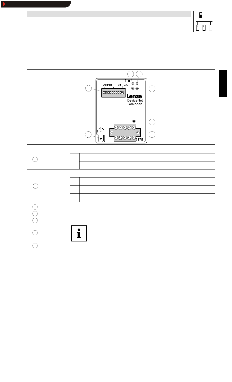
Components of the fieldbus module
1
6
5
3
2
4
7
Pos.
Designation
Meaning
Notes
St t
f th
OFF
2175 fieldbus module is not supplied with voltage; controller or external voltage supply is switched off.
1
Status of the
controller
connection
GREE
BLINKING
2175 fieldbus module is supplied with voltage but is not connected to the controller (controller is
switched off, in initialization or not available).
1
connection
(two-colour LED)
GREE
N
Constantly
ON
2175 fieldbus module is supplied with voltage and is connected to the controller.
OFF
•
No connection with the master
•
Fieldbus module is not supplied with voltage
2
Connection status
GREE
N
BLINKING
Dup_Mac_ID testing. Still no connection to the master.
2
Connection status
(two-colour LED)
GREE
N
ON
DeviceNet connection built up.
RED
BLINKING
No communication because time limit exceeded
RED
ON
Internal fault of the fieldbus module
3
Green and red drive
LEDs (drive)
Operating status of the following controllers: 82XX, 8200 vector, 93XX and servo PLC 9300
(see Operating Instructions for the controller)
4
Fixing screw
5
5-pole plug-in connector (see chapter 10.3.2)
6
Connection
PE shield cable
Only for 820X and 821X:
If necessary use an additional PE shield cable which avoids EMC-related communication interference
in especially noisy environments.
7
DIP switch
For settings see chapter 11
Show/Hide Bookmarks