3 electrical installation, Assignment of the plug/socket connector, Canopen – Lenze EMF2175IB User Manual
Page 19: 4installation, 1 assignment of the plug/ socket connector
CANopen
4
Installation
4-3
L
BA2175 EN 2.0
4.3
Electrical installation
Note!
The communication of 820X and 821X controllers can be interfered by electromagnetic
interferences.
If necessary, use an additional PE shield cable at position 6
(
^
4-1)
4.3.1
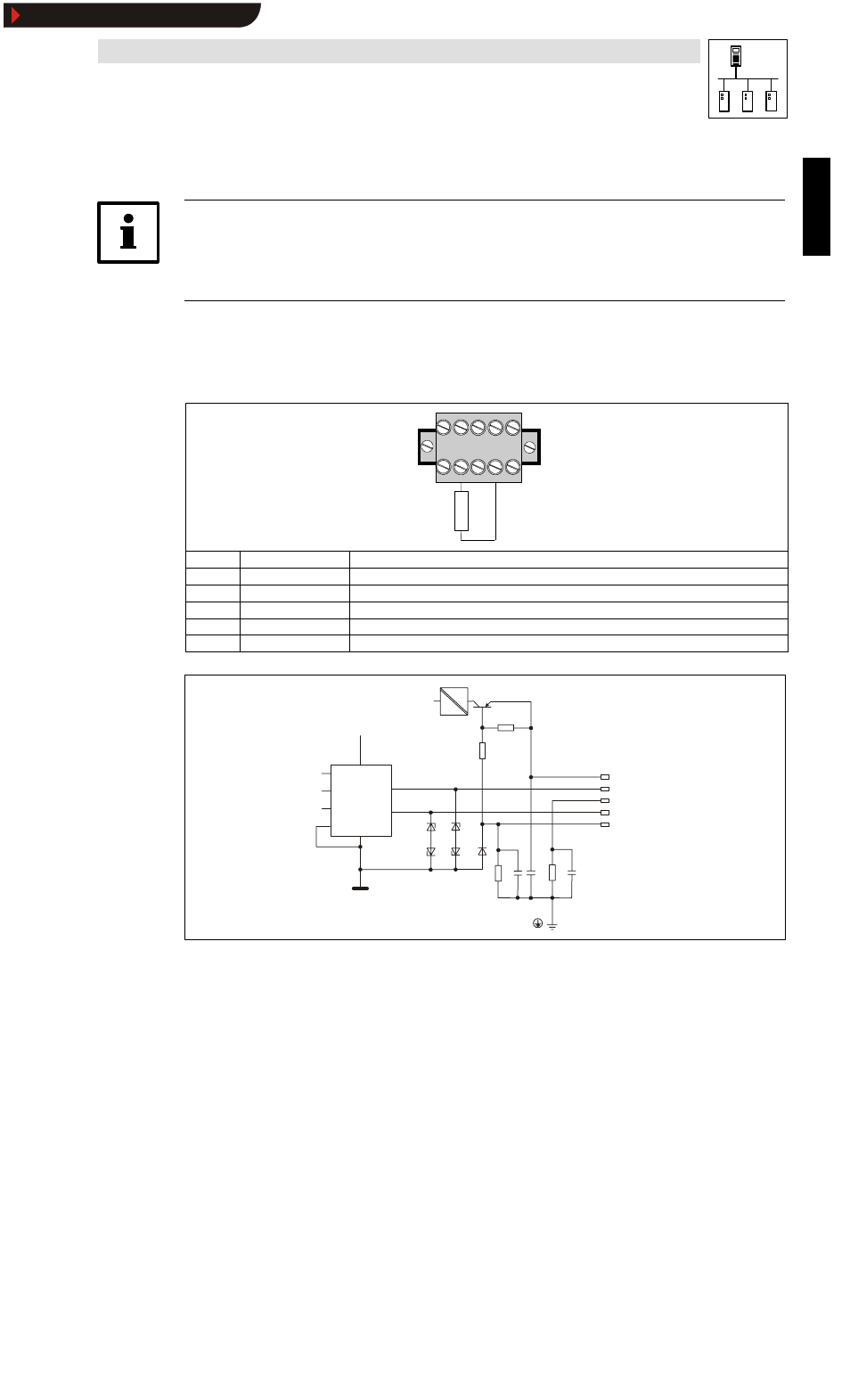
Assignment of the plug/ socket connector
The 2175 fieldbus module is connected to the bus through a 5 pole plug/socket connector.
5
4
3
2
1
2175
120R
Terminal
Designation
Explanation
1
V-
GND; reference for external voltage supply
2
CAN_L
Data cable / input for terminating resistance of 120 Ohm
3
SHIELD
Shield
4
CAN_H
Data cable / input for terminating resistance of 120 Ohm
5
V+
External voltage supply; see notes in chapter 10.3.3
2175DeN007
+Vcc
+V
cc
+V
CAN+
Shield
CAN-
- V
7
6
2
8
5
3
1
4
DC
DC
Fig. 4-1
Terminal assignment
Show/Hide Bookmarks
See also other documents in the category Lenze Hardware:
- ESMD smd tmd remote keypad (4 pages)
- EPM Programmer EEPM1RA (114 pages)
- ESMDC (36 pages)
- SMD Frequency Inverter 0.37kW-22kW (116 pages)
- SMD Frequency Inverter: Basic I/O with CANopen 0.25kW-4.0kW (36 pages)
- SMD 0-25kW-4-0kW (112 pages)
- smd Series Drives (32 pages)
- ESV SMV remote keypad H0 (2 pages)
- ESV SMV remote keypad H1 (2 pages)
- SV SMV additional I-O module (14 pages)
- EEPM1RA EPM (26 pages)
- SMVector RS-485 LECOM (29 pages)
- E84AYM10S (4 pages)
- E84AYCET EtherCAT MCI module (109 pages)
- EZAMBKBM (6 pages)
- E84AYCEC (89 pages)
- ERBPxxxRxxxx Brake resistor 200W-300W (134 pages)
- E84AYCPM (115 pages)
- E84AYCEO (165 pages)
- E84AYCER (94 pages)
- E84AVSCx 8400 StateLine C (76 pages)
- EZVxxxx-000 Power supply unit AC 230V 5A-20A (62 pages)
- E84AYCIB (75 pages)
- E82ZWBRB (48 pages)
- EZVxx00−001 Power supply unit AC 400V 5A-20A (64 pages)
- E82ZWBRE (64 pages)
- EZAEBK1001 (94 pages)
- E94AYAE SM301 (140 pages)
- E94AYAE SM301 (134 pages)
- E94AYAE SM301 (74 pages)
- E94AZPS (114 pages)
- E94AYCIB (78 pages)
- E94AYCIB (124 pages)
- E94AZEX100 (84 pages)
- EZS3-xxxA200 Sinusoidal filter 115-150A (44 pages)
- E94AZHA0051 (104 pages)
- E94AZCDM030 (72 pages)
- EZS3-xxxA200 Sinusoidal filter 180-480A (74 pages)
- E94AYCCA (188 pages)
- E94AYCCA (114 pages)
- E94AZHB0101 (104 pages)
- E94AYCPM (125 pages)
- E94AYCPM (114 pages)
- E94AYCET (140 pages)
- E94AYCET (103 pages)