Devicenet, 14 appendix, 1 devicenet commissioning example – Lenze EMF2175IB User Manual
Page 121
DeviceNet
14
Appendix
14-1
L
BA2175 EN 2.0
14
Appendix
14.1
DeviceNet commissioning example
2175DeN050
1747-
L541
1747-
IB32
1747-
OB32
DC
24V
0 1 2 3 4
5
6
7
8
9
1
2
RS232
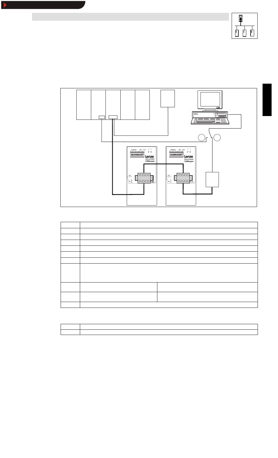
Tab. 14-1
Overview over the hardware and software used
Position
Module
0
Power supply, type: SLC 500 modular chassis (1746-A4)
1
SLC 5/04 CPU type: SLC 5/04 CPU (1747-L541)
2
DeviceNet scanner type: DeviceNet scanner (1747-SDN scanner module)
3
Digital input type: 32 digital input (1746-IB32)
4
Digital output typ: 32 digital output (1746-OB32)
5
External voltage supply for DeviceNet
6
PC with Allen-Bradley software:
•
RSLinx (revision 2.20.02)
•
RSNetworx (revision 3.00)
•
RSLogix (revision 4.10.01
7
Controller type: 8200vector, node 28
Setpoint selection via process data channel of the 2175 fieldbus
module: C0001 = 3
8
Controller type: 9300 servo inverter, node 34
Setpoint selection via process data channel of the 2175 fieldbus module
C0005 = xxx3
9
RS232 interface module type, 1770-KFD
Parameter setting for communication via DeviceNet:
Program transfer to CPU
DeviceNet configuration
According to the DeviceNet specification, thin cables
(
^
10-7)
have been used for wiring.
Show/Hide Bookmarks