Devicenet, 14 appendix, 7 lad34 - expl_btr – Lenze EMF2175IB User Manual
Page 148
DeviceNet
14
Appendix
14-28
L
BA2175 EN 2.0
14.3.7
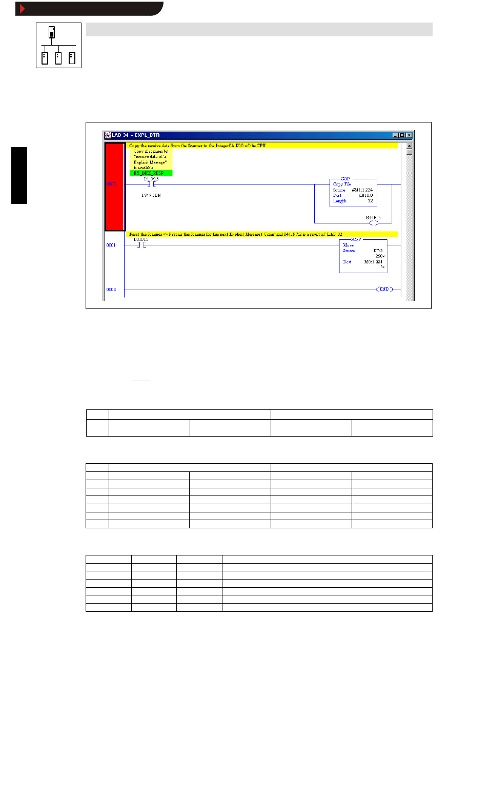
LAD34 - EXPL_BTR
The scanner content is read.
2175DeN107
Scanner status bit 15 indicates that a response is available in scanner area M1:1. The scanner status
bit activates the copy command and sets a marker bit.
The marker bit activates the scanner reset to ensure the next order.
The scanner input area is copied to the data area N10:0 with 32 words, i.e. the data received from
the scanner are saved. The data can be processed from the data word N10:0.
The scanner must be reset for the next order.
This is achieved by writing the reset command for the corresponding order and TXID, e.g. 0104
hex.
The order is reset with TXID 01.
Word
High byte
Low byte
0
TXID =
01
Order No. (e.g. 01)
Command =
04
01= Execute block
04= Clear response buffer
The read order response in N10:0 has the following structure:
Word
High byte
Low byte
0
TXID
01 (order No.)
Status
01 = Transaction successful
1
Port
00 (with SLC only 0)
Size
0E (user data size [byte])
2
Service
MAC ID
DeviceNet node address
3
L-code
00
L-code
0C
4
00
Subcode
00
5
Value
LOW word
Value
LOW word
6
Value
HIGH word
Value
HIGH word
Response to write request of code L-C0012 = 2.5sec:
N10:0
0101
TXID + status
01 (order No.) + 01(status): Transaction successful
N10:1
0008
Port + size
00 (port) + 08 (size, 8 bytes user data)
N10:2
8E1C
Service + Mac ID 8E (service) + 1C (Mac ID): 28 (node address)
N10:3
000C
L code
000C: L-C0012 (acceleration time)
N10:4
0000
Subcode
No subcode
N10:5
61A8
LOW word value 25000
≡
2.5 sec
N10:6
0000
HIGH word value 0000: End of user data
Show/Hide Bookmarks