Devicenet – Lenze EMF2175IB User Manual
Page 103
DeviceNet
10
Installation
10-5
L
BA2175 EN 2.0
A CAN line can have max. 63 devices. Devices are
•
connected controllers
•
masters
•
all components taking part in the communication
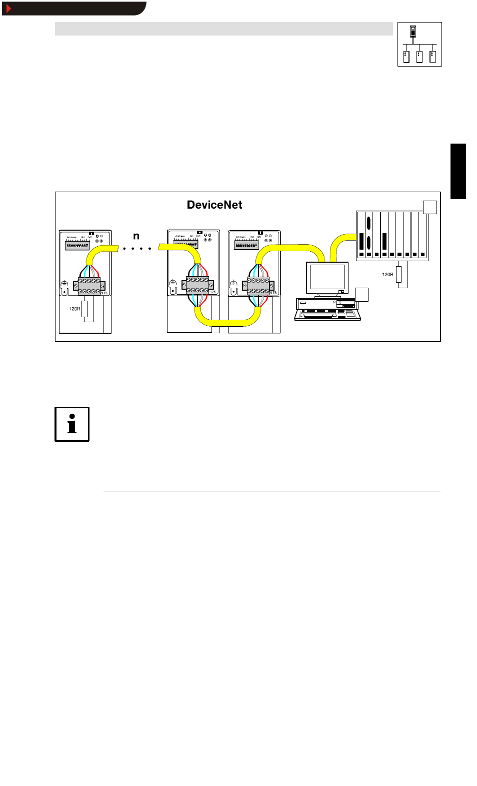
The following diagram shows a network:
By means of this network 8200 vector controllers with attached 2175 fieldbus modules
0
can
communicate with the DeviceNet master.
For easy configuration of the fieldbus modules a PC with “ DeviceNet Manager” software
1
can be
used.
2175DeN010
A
B
Fig. 10-1
DeviceNet line
The assignment of the plug/socket connector is described in chapter 10.3.2.
Chapter 9.5.1.3 informs about maximum cable lengths.
Not shown is the voltage supply required for the fieldbus modules.
Note!
Please take into consideration that
•
the shield of the DeviceNet cable is connected with each side
(plug/socket connector, connection: Shield).
•
a bus termination of 120 Ohm is available on both ends of the network.
•
the shield is connected to GND on the master side.
Show/Hide Bookmarks
- ESMD smd tmd remote keypad (4 pages)
- EPM Programmer EEPM1RA (114 pages)
- ESMDC (36 pages)
- SMD Frequency Inverter 0.37kW-22kW (116 pages)
- SMD Frequency Inverter: Basic I/O with CANopen 0.25kW-4.0kW (36 pages)
- SMD 0-25kW-4-0kW (112 pages)
- smd Series Drives (32 pages)
- ESV SMV remote keypad H0 (2 pages)
- ESV SMV remote keypad H1 (2 pages)
- SV SMV additional I-O module (14 pages)
- EEPM1RA EPM (26 pages)
- SMVector RS-485 LECOM (29 pages)
- E84AYM10S (4 pages)
- E84AYCET EtherCAT MCI module (109 pages)
- EZAMBKBM (6 pages)
- E84AYCEC (89 pages)
- ERBPxxxRxxxx Brake resistor 200W-300W (134 pages)
- E84AYCPM (115 pages)
- E84AYCEO (165 pages)
- E84AYCER (94 pages)
- E84AVSCx 8400 StateLine C (76 pages)
- EZVxxxx-000 Power supply unit AC 230V 5A-20A (62 pages)
- E84AYCIB (75 pages)
- E82ZWBRB (48 pages)
- EZVxx00−001 Power supply unit AC 400V 5A-20A (64 pages)
- E82ZWBRE (64 pages)
- EZAEBK1001 (94 pages)
- E94AYAE SM301 (134 pages)
- E94AYAE SM301 (74 pages)
- E94AYAE SM301 (140 pages)
- E94AZPS (114 pages)
- E94AYCIB (78 pages)
- E94AYCIB (124 pages)
- E94AZEX100 (84 pages)
- EZS3-xxxA200 Sinusoidal filter 115-150A (44 pages)
- E94AZHA0051 (104 pages)
- E94AZCDM030 (72 pages)
- EZS3-xxxA200 Sinusoidal filter 180-480A (74 pages)
- E94AYCCA (114 pages)
- E94AYCCA (188 pages)
- E94AZHB0101 (104 pages)
- E94AYCPM (125 pages)
- E94AYCPM (114 pages)
- E94AYCET (140 pages)
- E94AYCET (103 pages)