Red Lion IndustrialPr 6000 Router User Manual
Page 150
Software User Guide
150
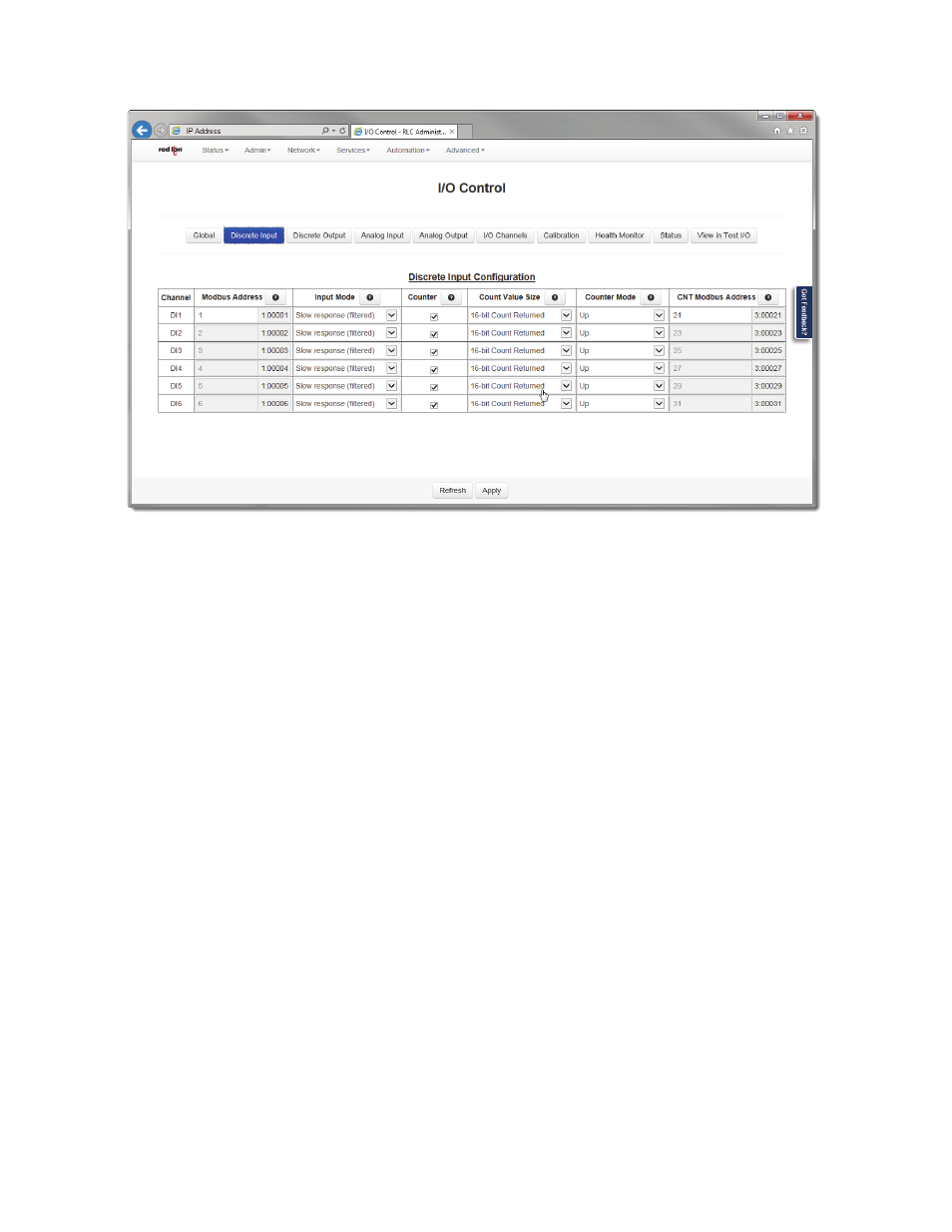
Automation Tab
Channel: A channel is a physical IO point that can be either analog or digital.
Modbus Address: Configuration must be sequential. Addresses are fixed sequentially from the base address.
Input Mode: This field defines the filtering mode of the Discrete Input channel. Select an option from the drop down
list.
Disabled: Selecting this option will completetly disable the channel and a zero (0) will be reported.
Slow Response (filtered): When this option is selected, the Discrete Input will have software filtering applied to the input.
Software filtering is suitable when the input is connected to a mechanical switch or relay because wil will eliminate contact
bounce. In this mode, counting is limited to a maximum of 10 Hz.
Fast Response (no filtering): When this option is selected, the discrete input will have no filtering applied to the input. This
option is suitable for solid state switches where no contact bounce is present.
Counter: This option will be available when Input Mode supports counters. When the checkbox is checked, the coun‐
ter mode is enabled. The Count Value Size, Counter Mode and CNT Starting Address become available and must be
configured as well. The counter value is stored in the CNT IODB address.
Count Value Size: This is a plain counter mode that is either 16 or 32‐bits in size, which counts on positive edge or neg‐
ative edge depending on the polarity bit.
16‐bit Count Returned: When this option is selected, the count will increment in a single register from 0 to 65535, then roll
over to 1 and continue to count upward again.
32‐bit Count Returned: Select this option to use two (2) consecutive 16‐bit registers as one 32‐bit register. When the first reg‐
ister rolls over to 1, the second register begins counting at 65536 (second register is most significant) and continues counting
upward in 32‐bit mode.
Note: Two (2) consecutive registers are always allocated in the “CNT IODB/Modbus Address” column whether set for 16‐bit or 32‐
bit mode. Therefore, when using 16‐bit Count Returned option, the second register should be ignored.
Counter Mode: When this option is selected, the counter mode must also be selected. If the 16‐bit Counter Returned
is selected, the analog input register increases from 0 to 32767, then ‐32768 to 0. If the 32‐bit Count Returned is