F-5-2 user defined connection, F-68, Udc mode window – Yokogawa FieldMate User Manual
Page 187
F-68
IM 01R01A01-01E
9th Edition : May 31, 2013-00
F-5-2 User Defined Connection
Built-in Connection supports the communication paths for HART, FOUNDATION
fieldbus, PROFIBUS, BRAIN and ISA100 direct connections. If you want to build a
communication path other than the HART, FOUNDATION fieldbus, PROFIBUS, and BRAIN
direct connections that are supported in Built-in Connection, you can use User Defined
Communication. If you want to use a communication protocol that is not supported
in Built-in Communication, you can also use User Defined Connection. If you want to
create a communication path and register a device using User Defined Connection, you
need to separately obtain and install the Comm DTM, Gateway DTM, Device DTM, or a
communication interface card if needed.
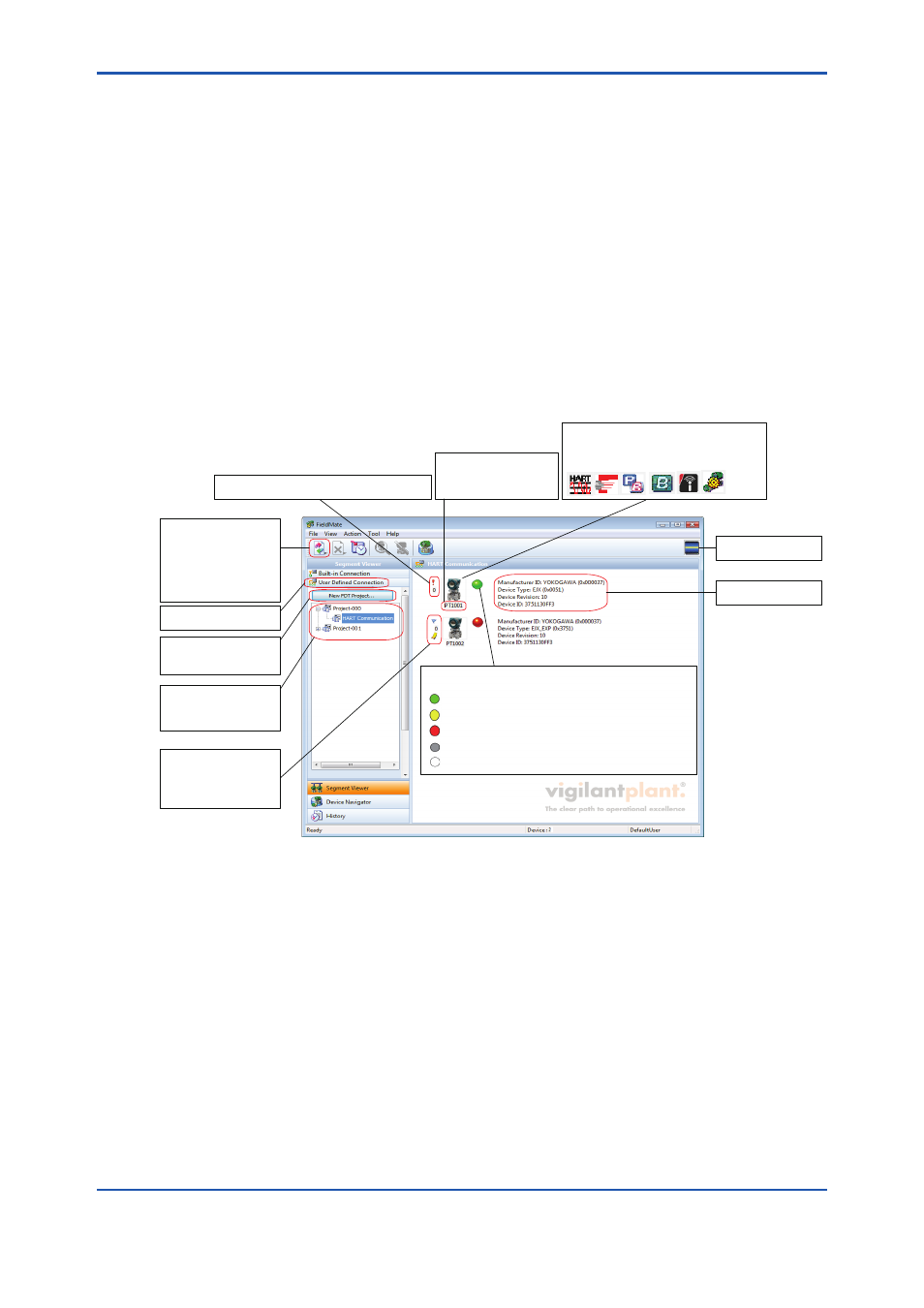
UDC Mode Window
An FDT Project is composed of a network topology of Comm DTM, Gateway DTM, and Device
DTM defined in DTM Works, and DTM data set for each DTM. The following shows the overview
of the FDT Project.
F050201E.ai
The Update button
refreshes the
information of the device
that is connected to the
currently displayed FDT
segment. The display is
updated.
Selecting this displays
nothing in the right panel.
Click this to open DTM
Works and create a new
FDT project.
Expand a project and
select a Comm DTM to
display the device DTM in
the right panel.
Icons that indicate Device
Flag or Memo Flag may
be displayed for devices
that are registered in the
database.
A red exclamation mark (!) is shown for devices
that are not registered in the database.
Displays either the live tag
of the device or the
configured device tag in
DTM Works.
Icons corresponding to the devices are
displayed. When there is no corresponding
icon, one of the following icons indicating
the communication type is displayed.
Communication status
is displayed.
Device information
is displayed.
Indicates the self-diagnostic result of only HART devices.
For other devices, there is no indication.
(Yellow): Warning, configuration error. Operation continues.
(Green): Normal
(Red): Abnormal, needs inspection (including replacing devices).
(Gray): Communication error, etc.
(White): Display of status icon is set to OFF.
Figure F-5-9
UDC Mode Window
The following describes the outline of the procedure for how to use User Defined Connection.
1. Install the Comm DTM, Gateway DTM, Device DTM, and a communication interface card
on a PC installed with FieldMate.
2. Update the DTM catalog in DTM Setup. *
3. Select User Defined Connection in Segment Viewer. Start DTM Works by selecting New
FDT Project.
4. Select and assign the Comm DTM and Gateway DTM from the list of installed Comm
DTMs, Gateway DTMs, and Device DTMs.
5. Configure the Comm DTM and Gateway DTM to create a communication path.
6. Select the Device DTM and assign the device.