IAI America RCM-101-USB User Manual
Page 138
11. Smart T
uning Function (V
ersion V8.03.00.00 or Later)
126
Fig. 11.6 Smart Tuning Setting Window (Function Invalid)
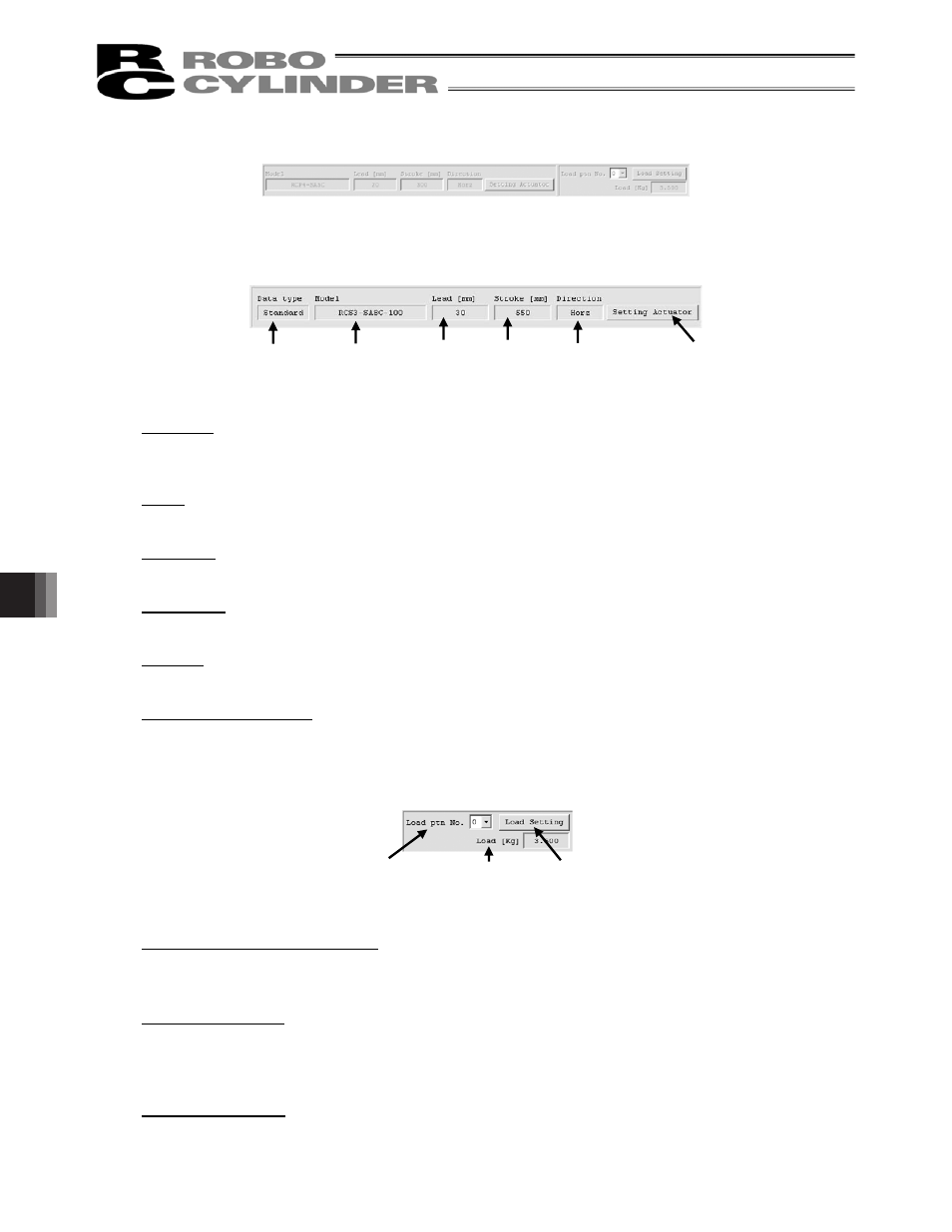
[2] Box to show actuator setting applicable for velocity and acceleration/deceleration settings
Fig. 11.7 Box to show actuator setting applicable for velocity and acceleration/deceleration settings
Data Type (Version V9.02.00.00 or later)
Data type can be selected from the standard and the special order if there is the actuator attribute data
file for the special order.
Model
In here, shows the model code of the actuator currently set to the controller.
Lead [mm]
In here, shows the actuator lead [mm] currently set to the controller.
Stroke [mm]
In here, shows the actuator stroke [mm] currently set to the controller.
Direction
In here, shows the posture of the actuator currently set to the controller.
Setting Actuator Button
Click here and “Actuator setting for Vel and Acc setting” window (Fig. 11.9) opens.
[3] Box to show carrier load setting for velocity and acceleration/deceleration settings
Fig. 11.8 Box to show carrier load setting for velocity and acceleration/deceleration settings
Carrier load pattern number select
Select the carrier load to be used for the velocity and acceleration/deceleration settings.
There are 4 options from 0 to 3 available to choose from.
Selected carrier load
In here, shows the carrier load set to the carrier load pattern number selected in the carrier load pattern
number select.
Fig. 11.8 shows the case of 3.500 [Kg] being set to Carrier Load No. 0.
Load Setting Button
Click here and “Load Setting for Vel and Acc setting” window (Fig. 11.10) opens.
Model
Direction
Lead
[mm]
Stroke
[mm]
Setting Actuator Button
Carrier load
number select
Selected carrier
load
Load Setting Button
Data type