IAI America RCM-101-USB User Manual
Page 123
8. Monitoring
111
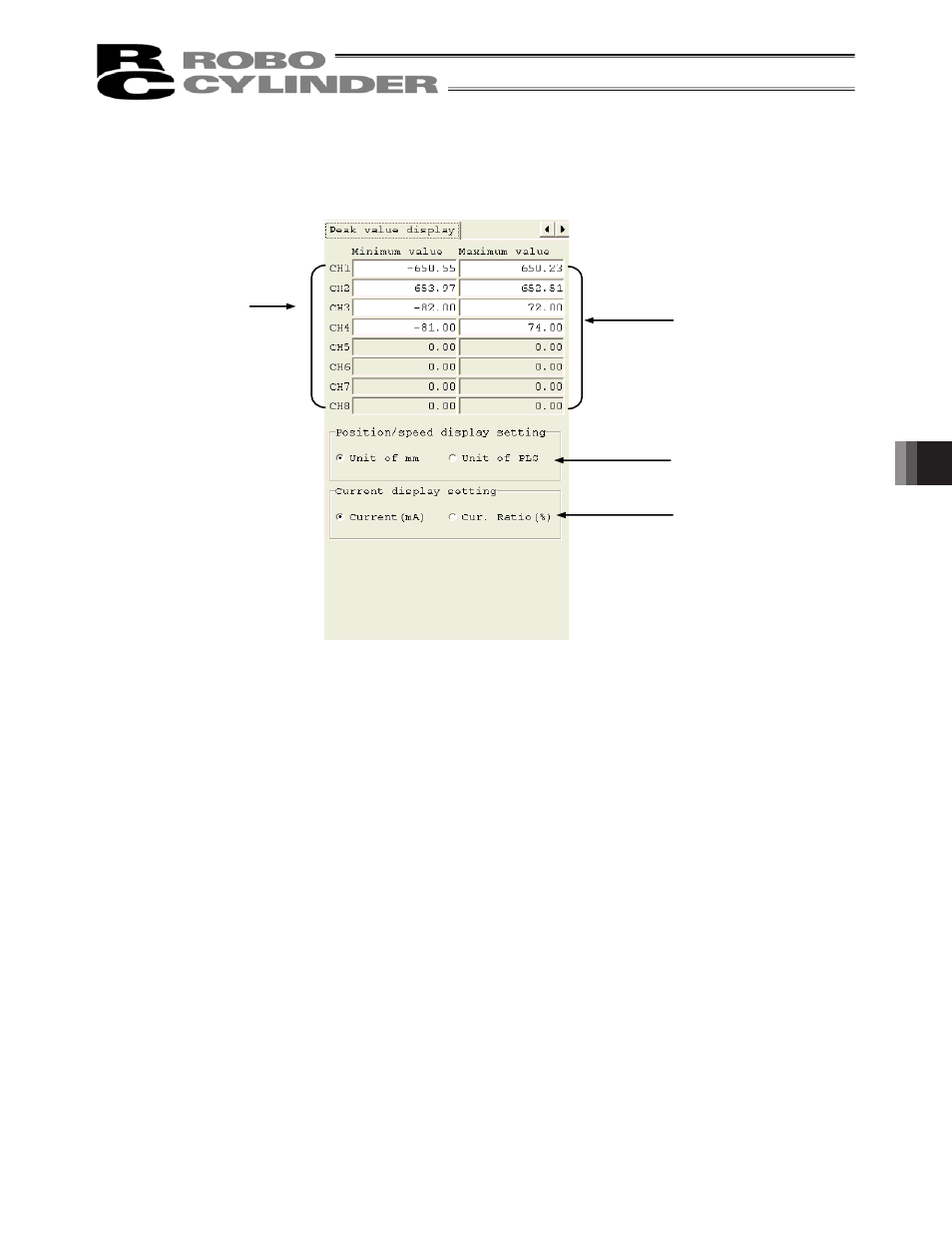
(3) Peak value display area
Fig. 8.17 Servo Monitor Window (Peak Value Display Area)
[1] Minimum value
The minimum value of data monitored on each channel is shown.
[2] Maximum value
The maximum value of data monitored on each channel is shown.
[3]
Position/speed display setting radio buttons
Select the display unit of position/speed data (mm or pls).
[4]
Current display setting radio buttons
Select the display unit of current data ([mA] or [% of rated current]).
[2]
[3]
[4]
[1]
This manual is related to the following products: