Electrical connections, Safety precautions, Power supply m12 – Burkert Type 8645 User Manual
Page 32: Profibus® m12 fieldbus connection, Configuration and function of the modules english, Profibus, M12 fieldbus connection fieldbus connection
2 - 8645
ConfiGuraTion anD funCTion of The moDules
English
Electrical connections
Safety Precautions
cAuTION!
The system is live. Working on the unit involves acute risk of injury.
Always switch off the power supply before starting work!
Observe all applicable accident prevention and safety regulations for electrical equipment.
Power Supply M12
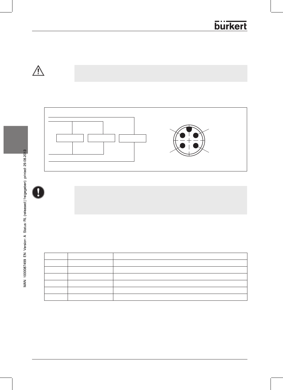
The 4-pin round plug for the power supply has the following pin assignment:
Electronics
Electronics
Outputs
24 V DC (1) Outputs
24 V DC (2)
Logic
GND ()
Logic
GND (4) Outputs
PIN 1
+24 V
driver (outputs)
PIN 4
GND
driver
PIN 2
+24 V
Logic
PIN
GND
Logic
Illustration: Power supply M12 – Fieldbus module PROFIBUS
PROFIBUS
®
NOTE!
• Protect pin 1 of the power supply with a 4 A (medium time-lag) fuse and pin 2 with a 1
A (medium time-lag) fuse.
• In order to ensure the electromagnetic compatibility (EMC) , connect screw termi-
nal FE (functional earthing) to earth potential using the shortest possible cable
(0 cm).
PROFIBuS
®
M12 Fieldbus connection
Fieldbus connection
The M12 plug-in system is used for the fieldbus connection. In order to avoid confusion between bus and
power supply slot, use the reserve key encoding here.
Allocation of the pins
pin No.
Signal
Relevance
1
VP
Power supply plus (P5V)
2
RxDx/TxD-N
Transmit / receive data N, A line
DGND
Data transmission potential (reference potential to VO)
4
RxDx/TxD-P
Transmit / receive data P, B line
5
Screen
Screen or protective earthing
Thread
Screen
Screen or protective earthing