Electrical connections, Configuration and function of the modules english – Burkert Type 8645 User Manual
Page 106
106 - 8645
ConfiGuraTion anD funCTion of The moDules
English
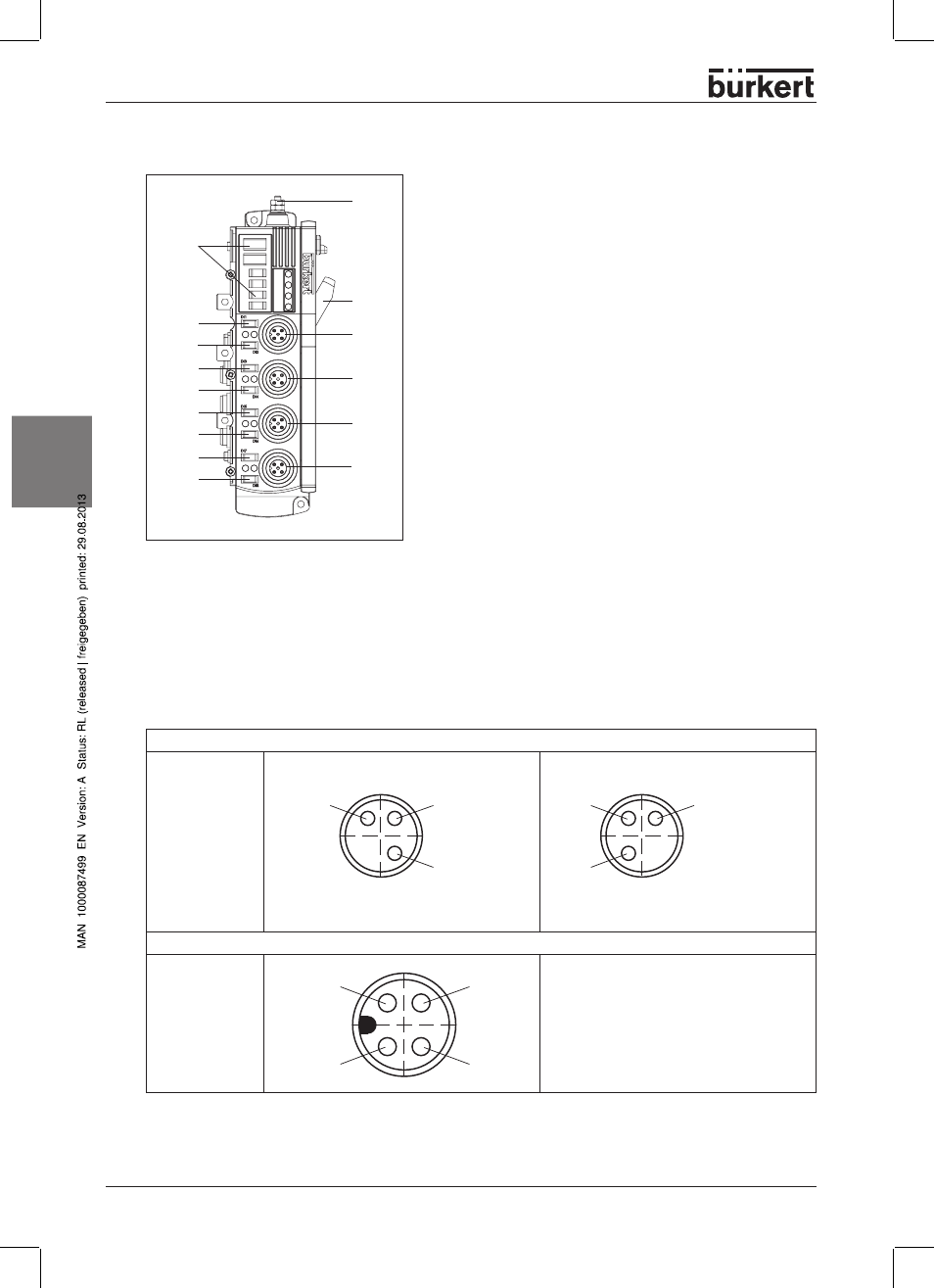
Electronic Module 8 dig�ital Inputs M12 (double allocation)
1
4
5
2
8
1
12
11
10
6
9
15
14
7
Legend
1
2
3
4
5
6
7
8
9
10
11
12
13
14
15
FE contact
Label panels
DIN rail mounting
Connection DI
1
/ DI
2
(M12)
Connection DI
3
/ DI
4
(M12)
Connection DI
5
/ DI
6
(M12)
Connection DI
7
/ DI
8
(M12)
Label panel DI
1
Label panel DI
2
Label panel DI
3
Label panel DI
4
Label panel DI
5
Label panel DI
6
Label panel DI
7
Label panel DI
8
Illustration: Electronic Module 8 Digital Inputs M12 (double allocation)
Electrical connections
The pins of the round plug connectors are allocated as follows:
Allocation M8
Pin 1: 24 V
Pin : GND
Pin 4: IN X
PIN 4
IN X
PIN 1
+24 V
transmitter
PIN
GND
transmitter
PIN 1
+24 V
transmitter
PIN 4
IN X
PIN
GND
transmitter
Allocation M12
Pin 1: 24 V
Pin 2: IN (X+1)
Pin : GND
Pin 4: IN X
PIN
GND
transmitter
PIN 4
IN X
PIN 2
IN (X+1)
PIN 1
+24 V
transmitter