Atmega163(l) – Rainbow Electronics ATmega163L User Manual
Page 93
ATmega163(L)
93
switched on (ADEN in ADCSR is set). Additionally, when changing voltage reference, the user may improve accuracy by
disregarding the first conversion result after the reference or MUX setting was changed.
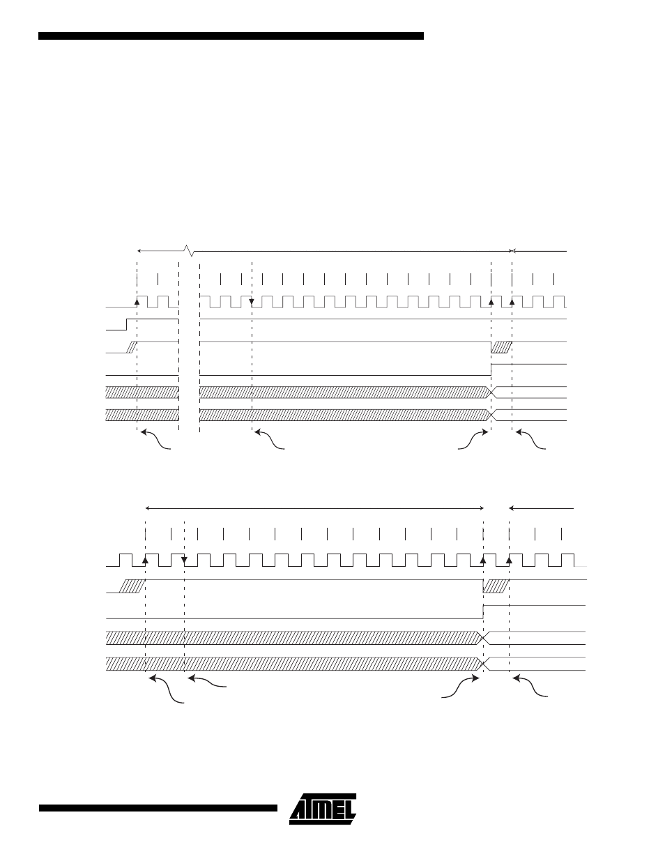
The actual sample-and-hold takes place 1.5 ADC clock cycles after the start of a normal conversion and 13.5 ADC clock
cycles after the start of an extended conversion. When a conversion is complete, the result is written to the ADC data reg-
isters, and ADIF is set. In single conversion mode, ADSC is cleared simultaneously. The software may then set ADSC
again, and a new conversion will be initated on the first rising ADC clock edge. In Free Running Mode, a new conversion
will be started immediately after the conversion completes, while ADSC remains high. Using Free Running Mode and an
ADC clock frequency of 200 kHz gives the lowest conversion time with a maximum resolution, 65
µs, equivalent to 15
kSPS. For a summary of conversion times, see Table 39.
Figure 59. ADC Timing Diagram, Extended Conversion (Single Conversion Mode)
Figure 60. ADC Timing Diagram, Single Conversion
Sign and MSB of result
LSB of result
ADC clock
ADSC
Sample & hold
ADIF
ADCH
ADCL
Cycle number
ADEN
1
2
12
13
14
15
16
17
18
19
20
21
22
23
24
25
1
2
Extended Conversion
Next
Conversion
3
MUX and REFS
update
MUX and REFS
update
Conversion
complete
1
2
3
4
5
6
7
8
9
10
11
12
13
Sign and MSB of result
LSB of result
ADC clock
ADSC
ADIF
ADCH
ADCL
Cycle number
1
2
One Conversion
Next Conversion
3
Sample & hold
MUX and REFS
update
Conversion
complete
MUX and REFS
update