Wait for spm instruction to complete, Boot loader lock-bits, Atmega163(l) – Rainbow Electronics ATmega163L User Manual
Page 118
ATmega163(L)
118
Wait for SPM Instruction to Complete
Though the CPU is halted during page write, page erase or Lock bit write, for future compatibility, the user software must
poll for SPM complete by reading the SPMCR register and loop until the SPMEN bit is cleared after a programming opera-
tion. See “Assembly code example for a Boot Loader” on page 121 for a code example.
Instruction Word Read after Page Erase, Page Write, and Lock-bit Write
To ensure proper instruction pipelining after programming action (page erase, page write, or lock-bit write), the SPM
instruction must be followed with the sequence (.dw $FFFF - NOP) as shown below:
spm
.dw $FFFF
nop
If not, the instruction following SPM might fail. It is not necessary to add this sequence when the SPM instruction only loads
the temporary buffer.
Avoid Reading the Application Section During Self-programming
During self-programming (either page erase or page write), the user software should not read the application section. The
user software itself must prevent addressing this section during the self-programming operations. This implies that inter-
rupts must be disabled. Before addressing the application section after the programming is completed, for future
compatibility, the user software must write”10001” to the five LSB in SPMCR and execute SPM within four clock cycles.
Then the user software should verify that the ASB bit is cleared. See “Assembly code example for a Boot Loader” on page
121 for an example. Though the ASB and ASRE bits have no special function in this device, it is important for future code
compatibility that they are treated as described above.
Boot Loader Lock-bits
ATmega163 has two separate sets of Boot Lock Bits which can be set independently. This gives the user a unique flexibility
to select different levels of protection.
The user can select:
• To protect the entire Flash from a software update by the MCU
• To only protect the Boot Loader Flash section from a software update by the MCU
• To only protect application Flash section from a software update by the MCU
• Allowing software update in the entire Flash
See Table 52 and Table 53 for further details. The Boot Lock bits can be set in software and in Serial or Parallel Program-
ming mode, but they can only be cleared by a chip erase command.
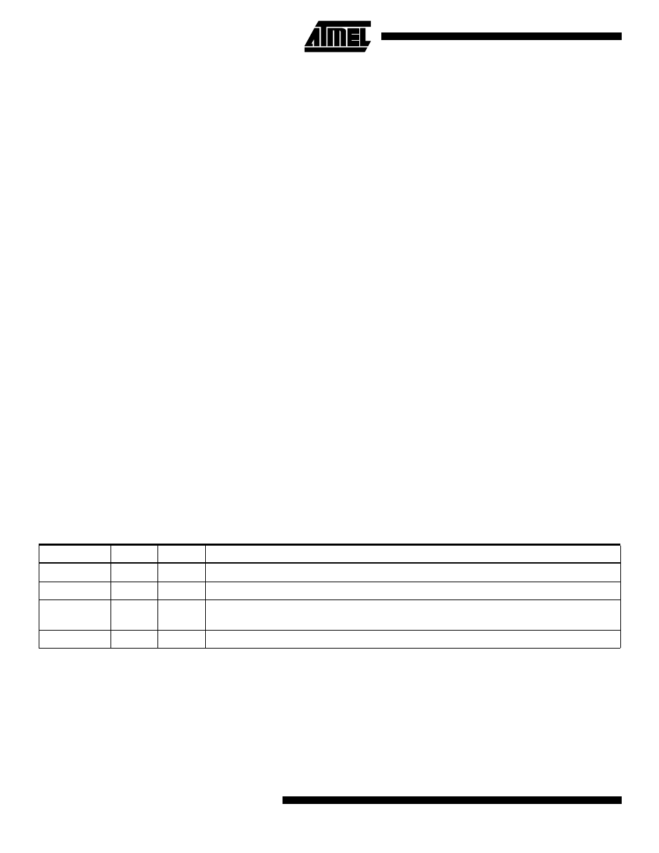
Table 52. Boot Lock Bit0 Protection Modes (Application Section)
Note:
‘1’ means unprogrammed, ‘0´means programmed
BLB0 mode
BLB02
BLB01
Protection
1
1
1
No restrictions for SPM, LPM accessing the Application section
2
1
0
SPM is not allowed to write to the Application section
3
0
0
SPM is not allowed to write to the Application section, and LPM executing from the Boot
Loader section is not allowed to read from the Application section
4
0
1
LPM executing from the Boot Loader section is not allowed to read from the Application section