Port d (pd7..pd0), Reset, Xtal1 – Rainbow Electronics ATmega163L User Manual
Page 5: Xtal2, Avcc, Aref, Agnd, Clock options, Internal rc oscillator, Atmega163(l)
ATmega163(L)
5
Port D (PD7..PD0)
Port D is an 8-bit bidirectional I/O port with internal pull-up resistors (selected for each bit). The Port D output buffers can
sink 20 mA. As inputs, Port D pins that are externally pulled low will source current if the pull-up resistors are activated. Port
D also serves the functions of various special features of the ATmega163 as listed on page 110. The Port D pins are
tristated when a reset condition becomes active, even if the clock is not running.
RESET
Reset input. A low level on this pin for more than 500 ns will generate a reset, even if the clock is not running. Shorter
pulses are not guaranteed to generate a reset.
XTAL1
Input to the inverting oscillator amplifier and input to the internal clock operating circuit.
XTAL2
Output from the inverting oscillator amplifier.
AVCC
This is the supply voltage pin for Port A and the A/D Converter. It should be externally connected to VCC, even if the ADC
is not used. If the ADC is used, it should be connected to VCC through a low-pass filter. See page 90 for details on opera-
tion of the ADC.
AREF
This is the analog reference input pin for the A/D Converter. For ADC operations, a voltage in the range 2.5V to AV
CC
can
be applied to this pin.
AGND
Analog ground. If the board has a separate analog ground plane, this pin should be connected to this ground plane. Other-
wise, connect to GND.
Clock Options
The device has the following clock source options, selectable by Flash fuse bits as shown:
Note:
“1” means unprogrammed, “0” means programmed.
The various choices for each clocking option give different start-up times as shown in Table 5 on page 22.
Internal RC Oscillator
The internal RC oscillator option is an on-chip oscillator running at a fixed frequency of nominally 1 MHz. If selected, the
device can operate with no external components. The device is shipped with this option selected. See “EEPROM
Read/Write Access” on page 53 for information on calibrating this oscillator.
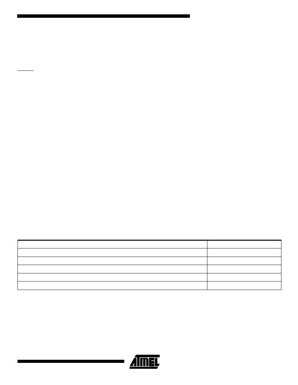
Table 1. Device Clocking Options Select
Device Clocking Option
CKSEL3..0
External Crystal/Ceramic Resonator
1111 - 1010
External Low-frequency Crystal
1001 - 1000
External RC Oscillator
0111 - 0101
Internal RC Oscillator
0100 - 0010
External Clock
0001 - 0000