Data reception, Atmega163(l) – Rainbow Electronics ATmega163L User Manual
Page 61
ATmega163(L)
61
• A new character has been written to UDR after the stop bit from the previous character has been shifted out. The shift
register is loaded immediately.
• A new character has been written to UDR before the stop bit from the previous character has been shifted out. The shift
register is loaded when the stop bit of the character currently being transmitted has been shifted out.
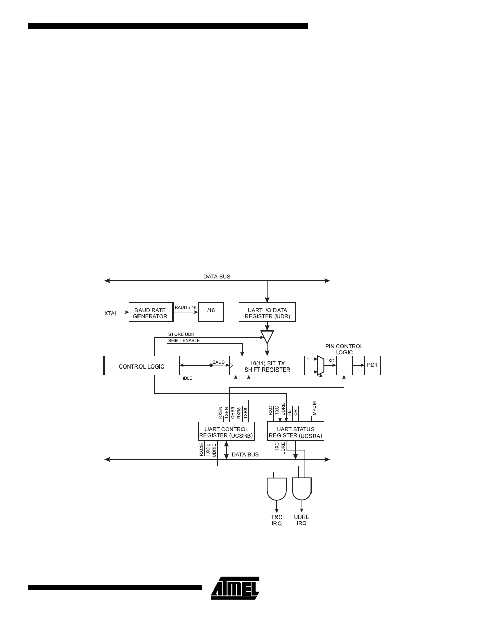
When data is transferred from UDR to the shift register, the UDRE (UART Data Register Empty) bit in the UART Status
Register, USR, is set. When this bit is set (one), the UART is ready to receive the next character. At the same time as the
data is transferred from UDR to the 10(11)-bit shift register, bit 0 of the shift register is cleared (start bit) and bit 9 or 10 is
set (stop bit). If 9 bit data word is selected (the CHR9 bit in the UART Control Register, UCR is set), the TXB8 bit in UCR is
transferred to bit 9 in the Transmit shift register.
On the Baud Rate clock following the transfer operation to the shift register, the start bit is shifted out on the TXD pin. Then
follows the data, LSB first. When the stop bit has been shifted out, the shift register is loaded if any new data has been writ-
ten to the UDR during the transmission. During loading, UDRE is set. If there is no new data in the UDR register to send
when the stop bit is shifted out, the UDRE flag will remain set until UDR is written again. When no new data has been writ-
ten, and the stop bit has been present on TXD for one bit length, the Transmit Complete Flag, TXC, in USR is set.
The TXEN bit in UCR enables the UART transmitter when set (one). When this bit is cleared (zero), the PD1 pin can be
used for general I/O. When TXEN is set, the UART Transmitter will be connected to PD1, which is forced to be an output
pin regardless of the setting of the DDD1 bit in DDRD.
Data Reception
Figure 46 shows a block diagram of the UART Receiver
Figure 46. UART Receiver
The receiver front-end logic samples the signal on the RXD pin at a frequency 16 times the baud rate. While the line is idle,
one single sample of logical zero will be interpreted as the falling edge of a start bit, and the start bit detection sequence is
initiated. Let sample 1 denote the first zero-sample. Following the 1 to 0-transition, the receiver samples the RXD pin at