Atmega163(l) – Rainbow Electronics ATmega163L User Manual
Page 47
ATmega163(L)
47
If CTC2 is set and PWM mode is selected, the Timer/Counters will wrap and start counting from $00 after reaching $FF.
The PD7(OC2) pin will be set or cleared according to the settings of COM21/COM20 on a Timer/Counter overflow or when
the counter value matches the contents of the Output Compare Register. Refer to Table 21 for details.
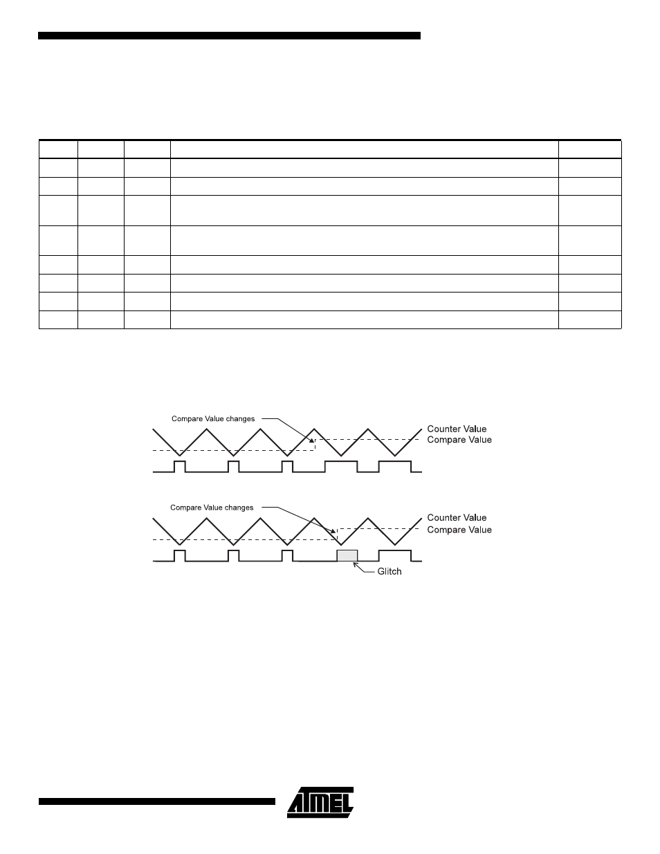
Note that in PWM mode, the value to be written to the Output Compare Register is first transferred to a temporary location,
and then latched into OCR2 when the Timer/Counter reaches $FF. This prevents the occurrence of odd-length PWM
pulses (glitches) in the event of an unsynchronized OCR2 write. See Figure 38 for examples.
Figure 38. Effects of Unsynchronized OCR Latching
Table 21. Compare Mode Select in PWM Mode
CTC2
COM21
COM20
Effect on Compare Pin
Frequency
0
0
0
Not connected
0
0
1
Not connected
0
1
0
Cleared on compare match, up-counting. Set on compare match, down-counting (non-
inverted PWM).
f
TCK0/2
/510
0
1
1
Cleared on compare match, down-counting. Set on compare match, up-counting
(inverted PWM).
f
TCK0/2
/510
1
0
0
Not connected
1
0
1
Not connected
1
1
0
Cleared on compare match, set on overflow.
f
TCK0/2
/256
1
1
1
Set on compare match, cleared on overflow.
f
TCK0/2
/256
PWM Output OC2
PWM Output OC2
Unsynchronized OC2 Latch
Synchronized OC2 Latch