Wire serial interface (byte oriented), Atmega163(l) – Rainbow Electronics ATmega163L User Manual
Page 68
ATmega163(L)
68
2-wire Serial Interface (Byte Oriented)
The 2-wire Serial Interface supports bi-directional serial communication. It is designed primarily for simple but efficient inte-
grated circuit (IC) control. The system is comprised of two lines, SCL (Serial Clock) and SDA (Serial Data) that carry
information between the ICs connected to them. Various communication configurations can be designed using this bus.
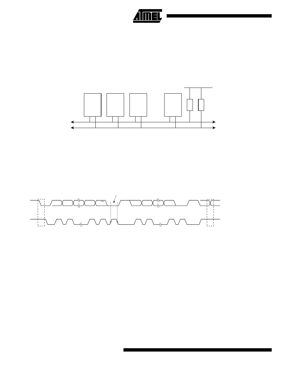
Figure 49 shows a typical 2-wire Serial Bus configuration. Any device connected to the bus can be master or slave. Note
that all AVR devices connected to the bus must be powered to allow any bus operation.
Figure 49. 2-wire Serial Bus Configuration
The 2-wire Serial Interface supports Master/Slave and Transmitter/Receiver operation at up to 400 kHz bus clock rate. The
2-wire Serial Interface has hardware support for 7 bit addressing, but is easily extended to e.g. a 10 bit addressing format
in software. When the 2-wire Serial Interface is enabled (TWEN in TWCR is set), a glitch filter is enabled for the input sig-
nals from the pins PC0 (SCL) and PC1 (SDA), and the output from these pins is slew-rate controlled. The 2-wire Serial
Interface is byte oriented. The operation of the 2-wire Serial Bus is shown as a pulse diagram in Figure 50, including the
START and STOP conditions and generation of ACK signal by the bus receiver.
Figure 50. 2-wire Serial Bus Timing Diagram
The block diagram of the 2-wire Serial Interface is shown in Figure 51.
Device 1
Device 2
Device 3
Device n
.......
V
CC
R1
R2
SCL
SDA
SDA
SCL
MSB
R/W
BIT
STOP CONDITION
START
CONDITION
REPEATED START CONDITION
1
2
7
8
9
1
2
8
9
ACK
ACK
ACKNOWLEDGE
FROM RECEIVER