Setting the boot loader lock bits by spm, Reading the fuse and lock bits from software, Nd table 53 – Rainbow Electronics ATmega163L User Manual
Page 119: Atmega163(l)
ATmega163(L)
119
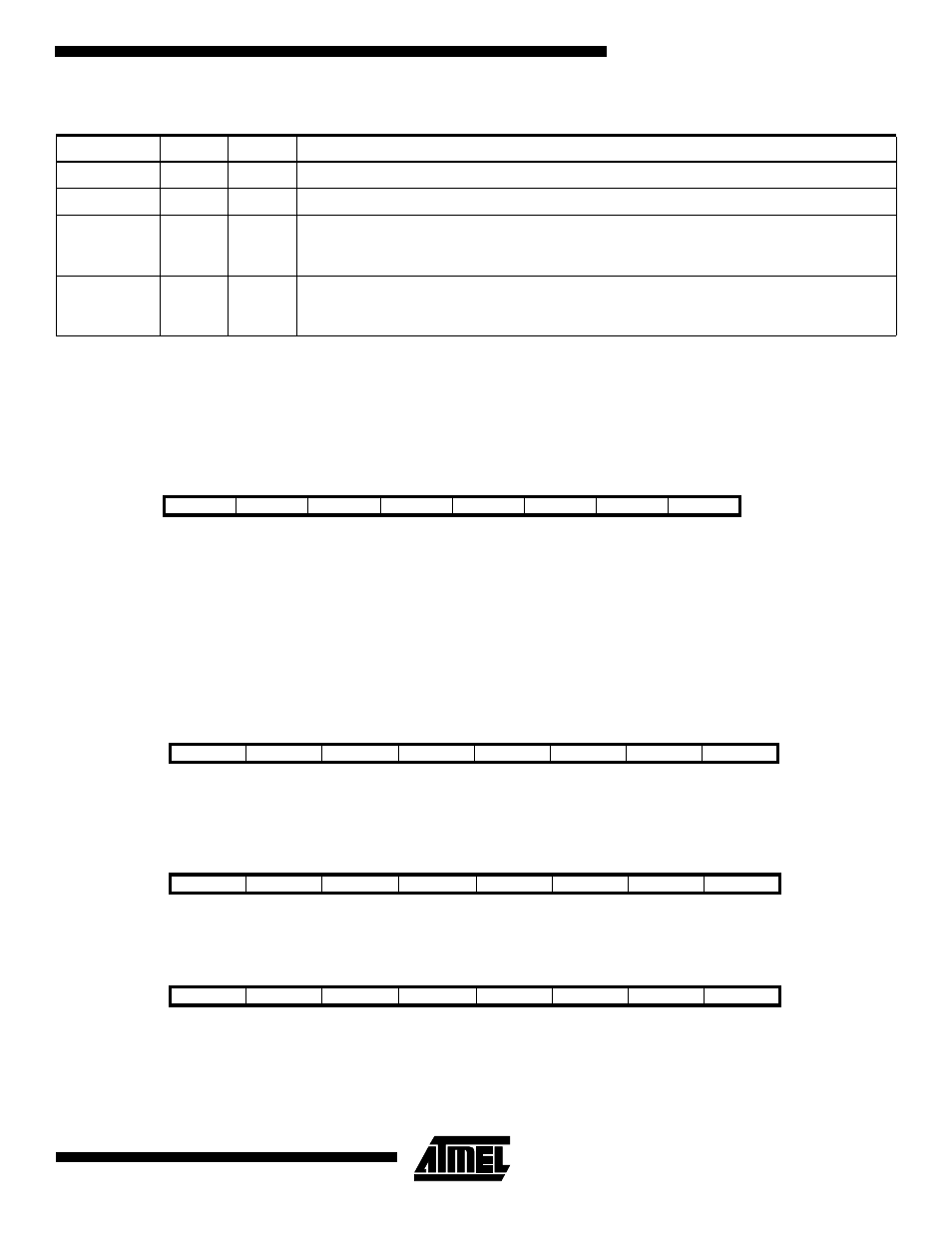
Table 53. Boot Lock Bit1 Protection Modes (Boot Loader Section)
‘1’ means unprogrammed, ‘0´means programmed
Setting the Boot Loader Lock Bits by SPM
To set the Boot Loader Lock bits, write the desired data to R0, write "00001001" to SPMCR and execute SPM within four
clock cycles after writing SPMCR. The only accessible lock bits are the Boot Lock bits that may prevent the Application and
Boot Loader section from any software update by the MCU.
If bits 5..2 in R0 are cleared (zero), the corresponding Boot Lock Bit will be programmed if an SPM instruction is executed
within four cycles after BLBSET and SPMEN are set in SPMCR.
Reading the Fuse and Lock Bits from Software
It is possible to read both the Fuse and Lock bits from software. To read the Lock bits, load the Z pointer with $0001 and set
the BLBSET and SPMEN bits in SPMCR. When an LPM instruction is executed within five CPU cycles after the BLBSET
and SPMEN bits are set in SPMCR, the value of the Lock bits will be loaded in the destination register. The BLBSET and
SPMEN bits will auto-clear upon completion of reading the Lock bits or if no SPM, or LPM, instruction is executed within
four, respectively five, CPU cycles. When BLBSET and SPMEN are cleared, LPM will work as described in “Constant
Addressing Using The LPM and SPM Instructions” on page 14 and in the Instruction set Manual.
The algorithm for reading the Fuse Low bits is similar to the one described above for reading the Lock bits. To read the
Fuse Low bits, load the Z pointer with $0000 and set the BLBSET and SPMEN bits in SPMCR. When an LPM instruction is
executed within five cycles after the BLBSET and SPMEN bits are set in the SPMCR, the value of the Fuse Low bits will be
loaded in the destination register as shown below.
Similarly, when reading the Fuse High bits, load $0003 in the Z pointer. When an LPM instruction is executed within five
cycles after the BLBSET and SPMEN bits are set in the SPMCR, the value of the Fuse High bits will be loaded in the desti-
nation register as shown below.
Fuse and Lock bits that are programmed, will be read as zero. Fuse and Lock bits that are unprogrammed, will be read as
one.
In all cases, the read value of unused bit positions are undefined.
BLB1 mode
BLB12
BLB11
Protection
1
1
1
No restrictions for SPM, LPM accessing the Boot Loader section
2
1
0
SPM is not allowed to write to the Boot Loader section
3
0
0
SPM is not allowed to write to the Boot Loader section, and LPM executing from the
Application section is not allowed to read from the Boot Loader section. If code is executed
from Boot Section, the interrupts are disabled when BLB12 is programmed.
4
0
1
LPM executing from the Application section is not allowed to read from the Boot Loader
section. If code is executed from Boot Section, the interrupts are disabled when BLB12 is
programmed.
Bit
7
6
5
4
3
2
1
0
R0
1
1
BLB12
BLB11
BLB02
BLB01
1
1
Bit
7
6
5
4
3
2
1
0
Rd
-
-
BLB12
BLB11
BLB02
BLB01
LB2
LB1
Bit
7
6
5
4
3
2
1
0
Rd
BODLEVEL
BODEN
SPIEN
-
CKSEL3
CKSEL2
CKSEL1
CKSEL0
Bit
7
6
5
4
3
2
1
0
Rd
-
-
-
-
-
BOOTSZ1
BOOTSZ0
BOOTRST