Atmega163(l) – Rainbow Electronics ATmega163L User Manual
Page 42
ATmega163(L)
42
Note:
X = A or B
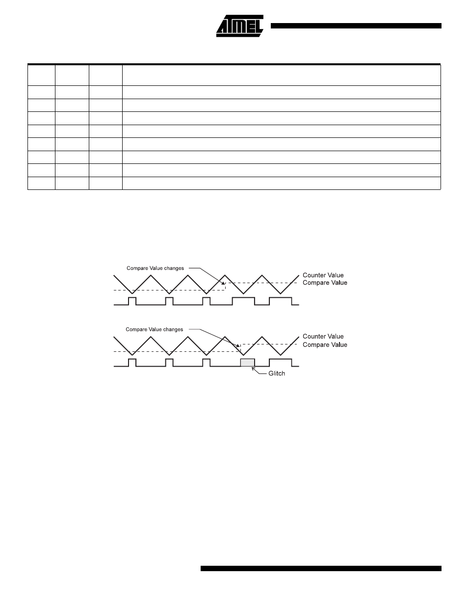
Note that in the PWM mode, the 8, 9, or 10 least significant OCR1A/OCR1B bits (depending on resolution), when written,
are transferred to a temporary location. They are latched when Timer/Counter1 reaches the value TOP. This prevents the
occurrence of odd-length PWM pulses (glitches) in the event of an unsynchronized OCR1A/OCR1B write. See Figure 35
and Figure 36 for an example in each mode.
Figure 35. Effects of Unsynchronized OCR1 Latching.
Table 17. Compare1 Mode Select in PWM Mode
CTC1
COM1X
1
COM1X
0
Effect on OCX1
0
0
0
Not connected
0
0
1
Not connected
0
1
0
Cleared on compare match, up-counting. Set on compare match, down-counting (non-inverted PWM).
0
1
1
Cleared on compare match, down-counting. Set on compare match, up-counting (inverted PWM).
1
0
0
Not connected
1
0
1
Not connected
1
1
0
Cleared on compare match, set on overflow.
1
1
1
Set on compare match, cleared on overflow.
PWM Output OC1x
PWM Output OC1x
Unsynchronized OC1x Latch
Synchronized OC1x Latch
Note: x = A or B