Alternate functions of portc, Port c schematics, Atmega163(l) – Rainbow Electronics ATmega163L User Manual
Page 107
ATmega163(L)
107
n: 7…0, pin number
Alternate Functions of PORTC
•
TOSC2 - PORTC, Bit 7
TOSC2, Timer Oscillator pin 2: When the AS2 bit in ASSR is set (one) to enable asynchronous clocking of Timer/Counter2,
pin PC7 is disconnected from the port, and becomes the inverting output of the oscillator amplifier. In this mode, a crystal
oscillator is connected to this pin, and the pin can not be used as an I/O pin.
•
TOSC1 - PORTC, Bit 6
TOSC1, Timer Oscillator pin 1: When the AS2 bit in ASSR is set (one) to enable asynchronous clocking of Timer/Counter1,
pin PC6 is disconnected from the port, and becomes the input of the inverting oscillator amplifier. In this mode, a crystal
oscillator is connected to this pin, and the pin can not be used as an I/O pin.
•
SDA - PORTC, Bit 1
SDA, 2-wire Serial Bus Data: When the TWEN bit in TWCR is set (one) to enable the 2-wire Serial Interface, pin PC1 is dis-
connected from the port and becomes the Serial Data I/O pin for the 2-wire Serial Interface. In this mode, there is a spike
filter on the pin to capture spikes shorter than 50 ns on the input signal, and the pin is driven by an open collector driver with
slew rate limitation.
•
SCL - PORTC, Bit 0
SCL, 2-wire Serial Interface Clock: When the TWEN bit in TWCR is set (one) to enable the 2-wire Serial Interface, pin PC1
is disconnected from the port and becomes the Serial Clock I/O pin for the 2-wire Serial Interface. In this mode, there is a
spike filter on the pin to capture spikes shorter than 50 ns on the input signal.
Port C Schematics
Note that all port pins are synchronized. The synchronization latches are not shown in the figure.
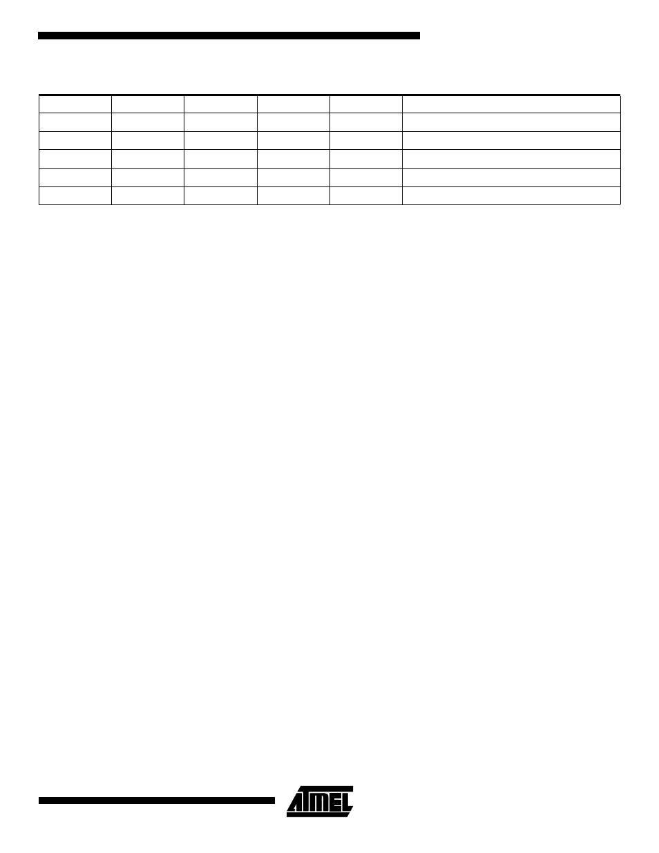
Table 47. DDCn Effects on PORT C Pins
DDCn
PORTCn
PUD
I/O
Pull Up
Comment
0
0
x
Input
No
Tri-state (Hi-Z)
0
1
1
Input
No
Tri-state (Hi-Z)
0
1
0
Input
Yes
PCn will source current if ext. pulled low.
1
0
x
Output
No
Push-pull Zero Output
1
1
x
Output
No
Push-pull One Output