Ss pin functionality, Atmega163(l) – Rainbow Electronics ATmega163L User Manual
Page 57
ATmega163(L)
57
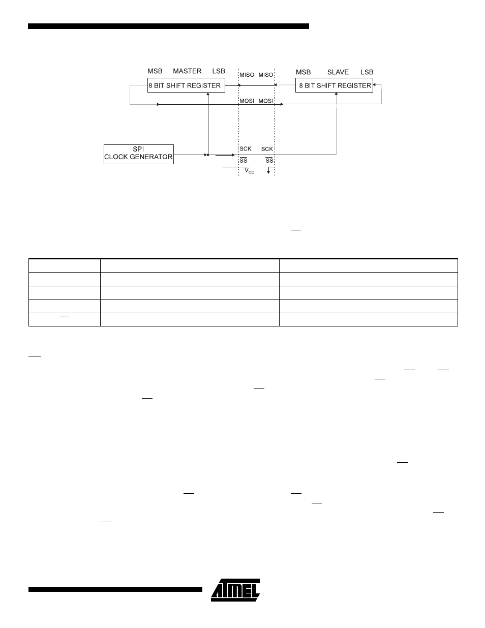
Figure 42. SPI Master-slave Interconnection
The system is single buffered in the transmit direction and double buffered in the receive direction. This means that bytes to
be transmitted cannot be written to the SPI Data Register before the entire shift cycle is completed. When receiving data,
however, a received character must be read from the SPI Data Register before the next character has been completely
shifted in. Otherwise, the first byte is lost.
When the SPI is enabled, the data direction of the MOSI, MISO, SCK, and SS pins is overridden according to Table 25.
Note:
See “Alternate Functions Of PORTB” on page 102 for a detailed description of how to define the direction of the user defined
SPI pins.
SS Pin Functionality
When the SPI is configured as a master (MSTR in SPCR is set), the user can determine the direction of the SS pin. If SS is
configured as an output, the pin is a general output pin which does not affect the SPI system. If SS is configured as an
input, it must be held high to ensure Master SPI operation. If the SS pin is driven low by peripheral circuitry when the SPI is
configured as a master with the SS pin defined as an input, the SPI system interprets this as another master selecting the
SPI as a slave and starting to send data to it. To avoid bus contention, the SPI system takes the following actions:
1.
The MSTR bit in SPCR is cleared and the SPI system becomes a slave. As a result of the SPI becoming a slave, the
MOSI and SCK pins become inputs.
2.
The SPIF flag in SPSR is set, and if the SPI interrupt is enabled, and the I-bit in SREG is set, the interrupt routine
will be executed.
Thus, when interrupt-driven SPI transmission is used in master mode, and there exists a possibility that SS is driven low,
the interrupt should always check that the MSTR bit is still set. If the MSTR bit has been cleared by a slave select, it must
be set by the user to re-enable SPI master mode.
When the SPI is configured as a slave, the SS pin is always input. When SS is held low, the SPI is activated, and MISO
becomes an output if configured so by the user. All other pins are inputs. When SS is driven high, all pins are inputs, and
the SPI is passive, which means that it will not receive incoming data. Note that the SPI logic will be reset once the SS pin
is driven high. If the SS pin is driven high during a transmission, the SPI will stop sending and receiving immediately and
both data received and data sent must be considered as lost.
Table 25. SPI Pin Overrides
Pin
Direction, Master SPI
Direction, Slave SPI
MOSI
User Defined
Input
MISO
Input
User Defined
SCK
User Defined
Input
SS
User Defined
Input