Uart baud rate registers - ubrr and ubrrhi, Double speed transmission, The baud rate generator in double uart speed mode – Rainbow Electronics ATmega163L User Manual
Page 66: Atmega163(l), Baud f, 8(ubr 1 )
ATmega163(L)
66
UART Baud Rate Registers - UBRR and UBRRHI
This is a 12-bit register which contains the UART Baud Rate according to the equation on the previous page. The UBRRHI
contains the 4 most significant bits, and the UBRR contains the 8 least significant bits of the UART Baud Rate.
Double Speed Transmission
The ATmega163 provides a separate UART mode which allows the user to double the communication speed. By setting
the U2X bit in the UART Control and Status Register UCSRA, the UART speed will be doubled. Note, however, that the
receiver will in this case only use half the number of samples (only 8 instead of 16) for data sampling and clock recovery,
and therefore requires more accurate baud rate setting and system clock.
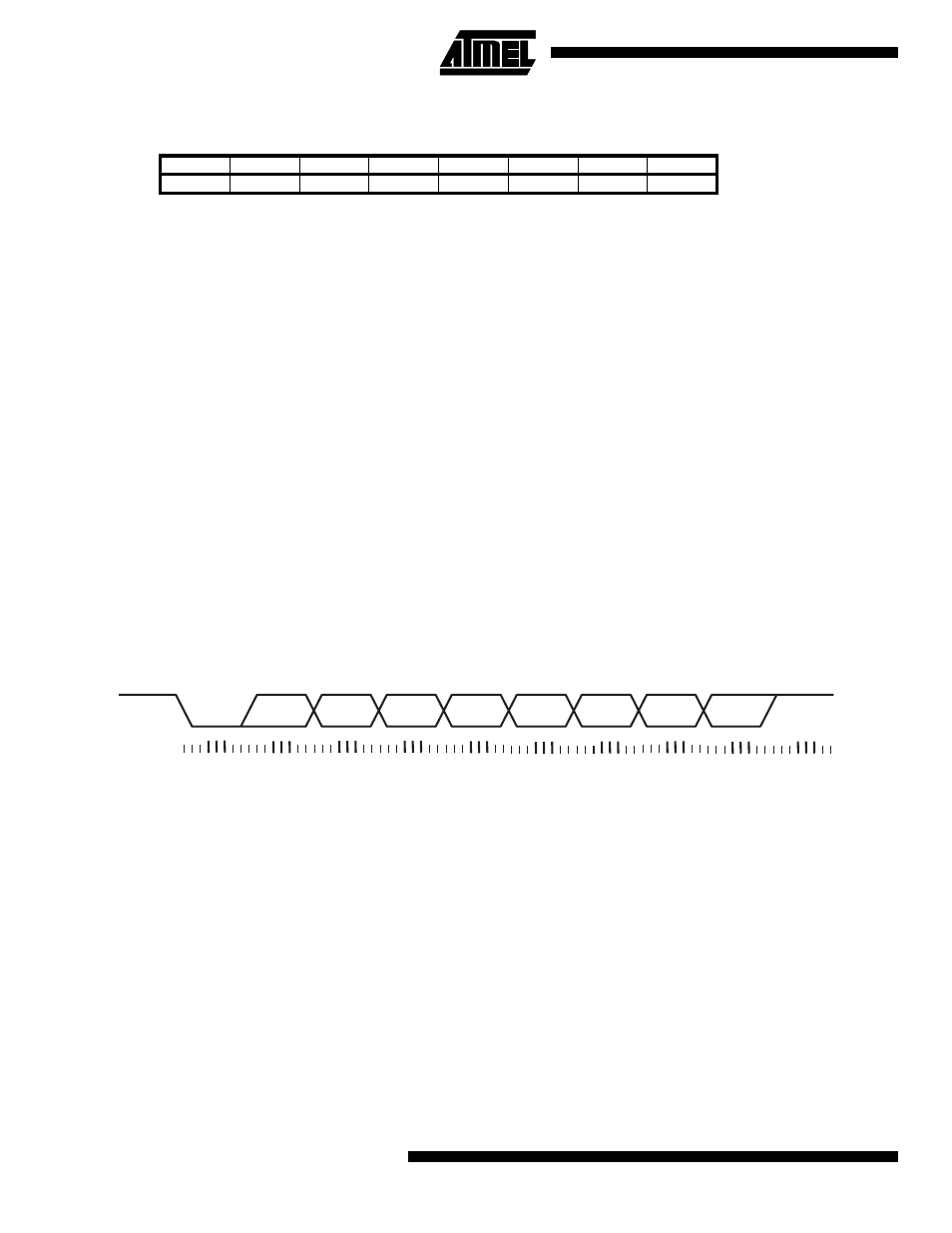
The data reception will differ slightly from normal mode. Since the speed is doubled, the receiver front-end logic samples
the signals on RXD pin at a frequency 8 times the baud rate. While the line is idle, one single sample of logical zero will be
interpreted as the falling edge of a start bit, and the start bit detection sequence is initiated. Let sample 1 denote the first
zero-sample. Following the 1 to 0-transition, the receiver samples the RXD pin at samples 4, 5, and 6. If two or more of
these three samples are found to be logical ones, the start bit is rejected as a noise spike and the receiver starts looking for
the next 1 to 0-transition.
If however, a valid start bit is detected, sampling of the data bits following the start bit is performed. These bits are also
sampled at samples 4, 5, and 6. The logical value found in at least two of the three samples is taken as the bit value. All bits
are shifted into the transmitter shift register as they are sampled. Sampling of an incoming character is shown in Figure 48.
Figure 48. Sampling Received Data When the Transmission Speed is Doubled
The Baud Rate Generator in Double UART Speed Mode
Note that the baud-rate equation is different from the equation on page 66 when the UART speed is doubled:
• BAUD = Baud-Rate
• f
CK
= Crystal Clock frequency
• UBR = Contents of the UBRRHI and UBRR registers, (0-4095)
• Note that this equation is only valid when the UART transmission speed is doubled.
For standard crystal frequencies, the most commonly used baud rates can be generated by using the UBR settings in
Table 28. UBR values which yield an actual baud rate differing less than 1.5% from the target baud rate, are bold in the
table. However, since the number of samples are reduced, and the system clock might have some variance (this applies
especially when using resonators), it is recommended that the baud rate error is less than 0.5%.
Bit
15
14
13
12
11
10
9
8
$20 ($40)
-
-
-
-
MSB
LSB
UBRRHI
$09 ($29)
MSB
LSB
UBRR
7
6
5
4
3
2
1
0
Read/Write
R
R
R
R
R/W
R/W
R/W
R/W
R/W
R/W
R/W
R/W
R/W
R/W
R/W
R/W
Initial value
0
0
0
0
0
0
0
0
0
0
0
0
0
0
0
0
START BIT
D0
D1
D2
D3
D4
D5
D6
D7
STOP BIT
RXD
RECEIVER
SAMPLING
BAUD
f
CK
8(UBR
1
)
+
------------------------------
=