Timer/counter1 - tcnt1h and tcnt1l, Tcnt1 timer/counter1 write, Tcnt1 timer/counter1 read – Rainbow Electronics ATmega163L User Manual
Page 39: Atmega163(l)
ATmega163(L)
39
... | C-1, C-1, C-1, C-1, C-1, C-1, C-1, C-1 | C, C, C, C, C, C, C, C | 0, 0, 0, 0, 0, 0, 0, 0 |1,1,1,1,1,1,1,1|...
In PWM mode, this bit has a different function. If the CTC1 bit is cleared in PWM mode, the Timer/Counter1 acts as an
up/down counter. If the CTC1 bit is set (one), the Timer/Counter wraps when it reaches the TOP value. Refer to page 41 for
a detailed description.
•
Bits 2..0 - CS12, CS11, CS10: Clock Select1, Bit 2,1, and 0
The Clock Select1 bits 2, 1, and 0 define the prescaling source of Timer/Counter1.
The Stop condition provides a Timer Enable/Disable function. The prescaled modes are scaled directly from the CK oscilla-
tor clock. If the external pin modes are used for Timer/Counter1, transitions on PB1/(T1) will clock the counter even if the
pin is configured as an output. This feature can give the user SW control of the counting.
Timer/Counter1 - TCNT1H and TCNT1L
This 16-bit register contains the prescaled value of the 16-bit Timer/Counter1. To ensure that both the high and low bytes
are read and written simultaneously when the CPU accesses these registers, the access is performed using an 8-bit tem-
porary register (TEMP). This temporary register is also used when accessing OCR1A, OCR1B, and ICR1. If the main
program and also interrupt routines perform access to registers using TEMP, interrupts must be disabled during access
from the main program and interrupt routines.
TCNT1 Timer/Counter1 Write:
When the CPU writes to the high byte TCNT1H, the written data is placed in the TEMP register. Next, when the CPU
writes the low byte TCNT1L, this byte of data is combined with the byte data in the TEMP register, and all 16 bits are
written to the TCNT1 Timer/Counter1 register simultaneously. Consequently, the high byte TCNT1H must be accessed
first for a full 16-bit register write operation.
TCNT1 Timer/Counter1 Read:
When the CPU reads the low byte TCNT1L, the data of the low byte TCNT1L is sent to the CPU and the data of the
high byte TCNT1H is placed in the TEMP register. When the CPU reads the data in the high byte TCNT1H, the CPU
receives the data in the TEMP register. Consequently, the low byte TCNT1L must be accessed first for a full 16-bit reg-
ister read operation.
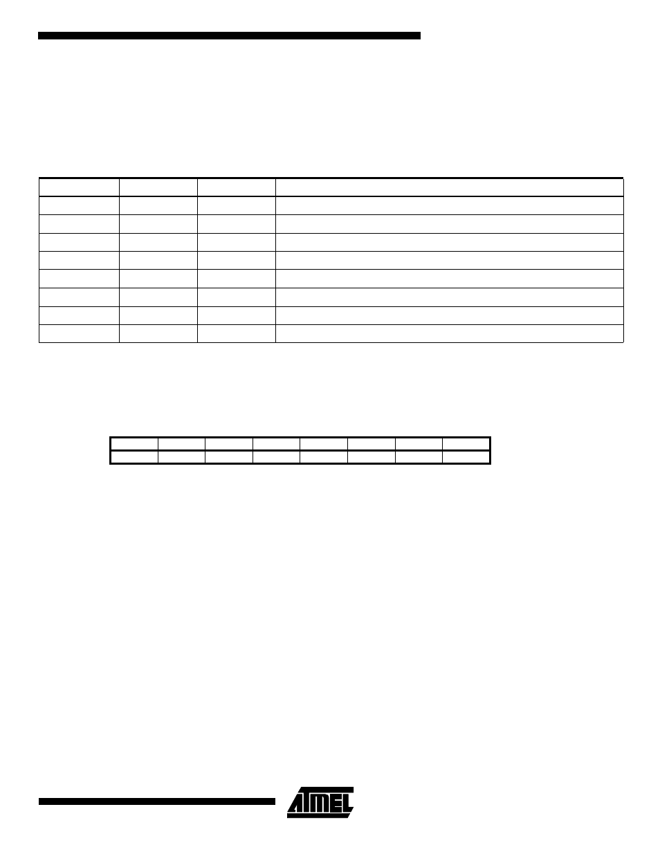
Table 14. Clock 1 Prescale Select
CS12
CS11
CS10
Description
0
0
0
Stop, the Timer/Counter1 is stopped.
0
0
1
CK
0
1
0
CK / 8
0
1
1
CK / 64
1
0
0
CK / 256
1
0
1
CK / 1024
1
1
0
External Pin T1, falling edge
1
1
1
External Pin T1, rising edge
Bit
15
14
13
12
11
10
9
8
$2D ($4D)
MSB
TCNT1H
$2C ($4C)
LSB
TCNT1L
7
6
5
4
3
2
1
0
Read/Write
R/W
R/W
R/W
R/W
R/W
R/W
R/W
R/W
R/W
R/W
R/W
R/W
R/W
R/W
R/W
R/W
Initial value
0
0
0
0
0
0
0
0
0
0
0
0
0
0
0
0