Eeprom write prevents writing to spmcr, Addressing the flash during self-programming, Store program memory control register - spmcr – Rainbow Electronics ATmega163L User Manual
Page 120: Atmega163(l)
ATmega163(L)
120
EEPROM Write Prevents Writing to SPMCR
Note that an EEPROM write operation will block all software programming to Flash. Reading the Fuses and Lock bits from
software will also be prevented during the EEPROM write operation. It is recommended that the user checks the status bit
(EEWE) in the EECR register and verifies that the bit is cleared before writing to the SPMCR register. If EEPROM writing is
performed inside an interrupt routine, the user software should disable that interrupt before checking the EEWE status bit.
Addressing the Flash During Self-programming
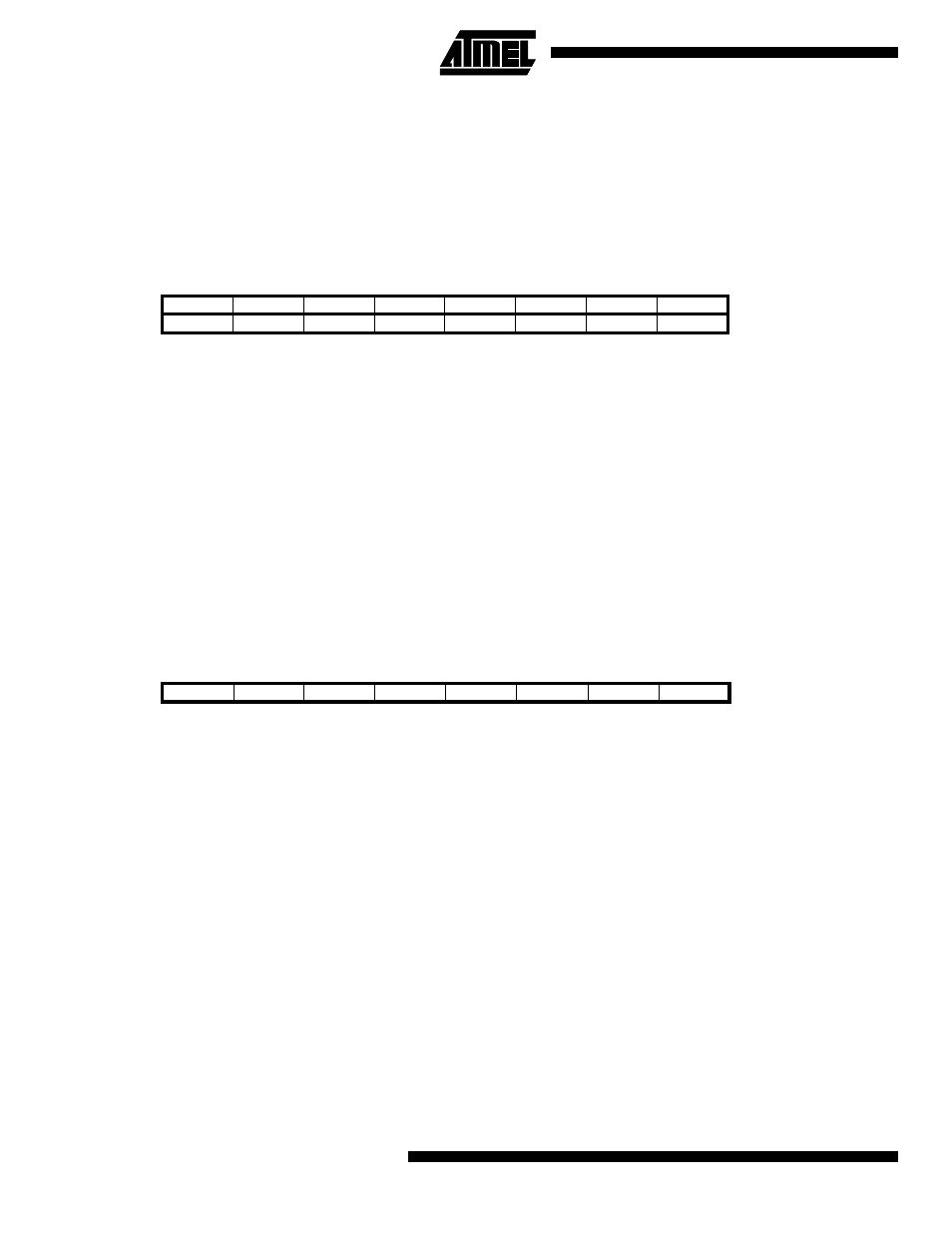
The Z pointer is used to address the SPM commands.
Z15:Z14 always ignored
Z13:Z7
page select, for page erase and page write
Z6:Z1
word select, for filling temp buffer (must be zero during page write operation)
Z0
should be zero for all SPM commands, byte select for the LPM instruction.
The only operation that does not use the Z pointer is Setting the Boot Loader Lock Bits. The content of the Z pointer is
ignored and will have no effect on the operation.
Note that the page erase and page write operation is addressed independently. Therefore it is of major importance that the
Boot Loader software addresses the same page in both the page erase and page write operation.
The LPM instruction also uses the Z pointer to store the address. Since this instruction addresses the Flash byte by byte,
also the LSB (bit Z0) of the Z pointer is used. See page 14 for a detailed description.
Store Program Memory Control Register - SPMCR
The Store Program Memory Control Register contains the control bits needed to control the programming of the Flash from
internal code execution.
•
Bit 7 - Res: Reserved Bit
This bit is a reserved bit in the ATmega163 and always reads as zero. This bit should be written to zero when writing
APMCR.
•
Bit 6 - ASB: Application Section Busy
Before entering the application section after a boot loader operation (page erase or page write) the user software must ver-
ify that this bit is cleared. In future devices, this bit will be set to “1” by page erase and page write. In ATmega163, this bit
always reads as zero.
•
Bit 5 - Res: Reserved Bit
This bit is a reserved bit in the ATmega163 and always reads as zero. This bit should be written to zero when writing
ASMCR.
•
Bit 4 - ASRE: Application Section Read Enable
Before re-entering the application section, the user software must set this bit together with the SPMEN bit and execute
SPM within 4 clock cycles.
•
Bit 3 - BLBSET: Boot Lock Bit Set
If this bit is set at the same time as SPMEN, the next SPM instruction within four clock cycles will set Boot Lock Bits. Alter-
natively, an LPM instruction within five cycles will read either the Lock Bits or the Fuse Bits. The BLBSET bit will auto-clear
upon completion of the SPM or LPM instruction, or if no SPM, or LPM, instruction is executed within four, respectively five,
clock cycles.
Bit
15
14
13
12
11
10
9
8
ZH (R31)
Z15
Z14
Z13
Z12
Z11
Z10
Z9
Z8
ZL (R30)
Z7
Z6
Z5
Z4
Z3
Z2
Z1
Z0
7
6
5
4
3
2
1
0
Bit
7
6
5
4
3
2
1
0
$37 ($57)
-
ASB
-
ASRE
BLBSET
PGWRT
PGERS
SPMEN
SPMCR
Read/Write
R
R
R
R/W
R/W
R/W
R/W
R/W
Initial value
x
0
0
0
0
0
0
0