Atmega163(l) – Rainbow Electronics ATmega163L User Manual
Page 69
ATmega163(L)
69
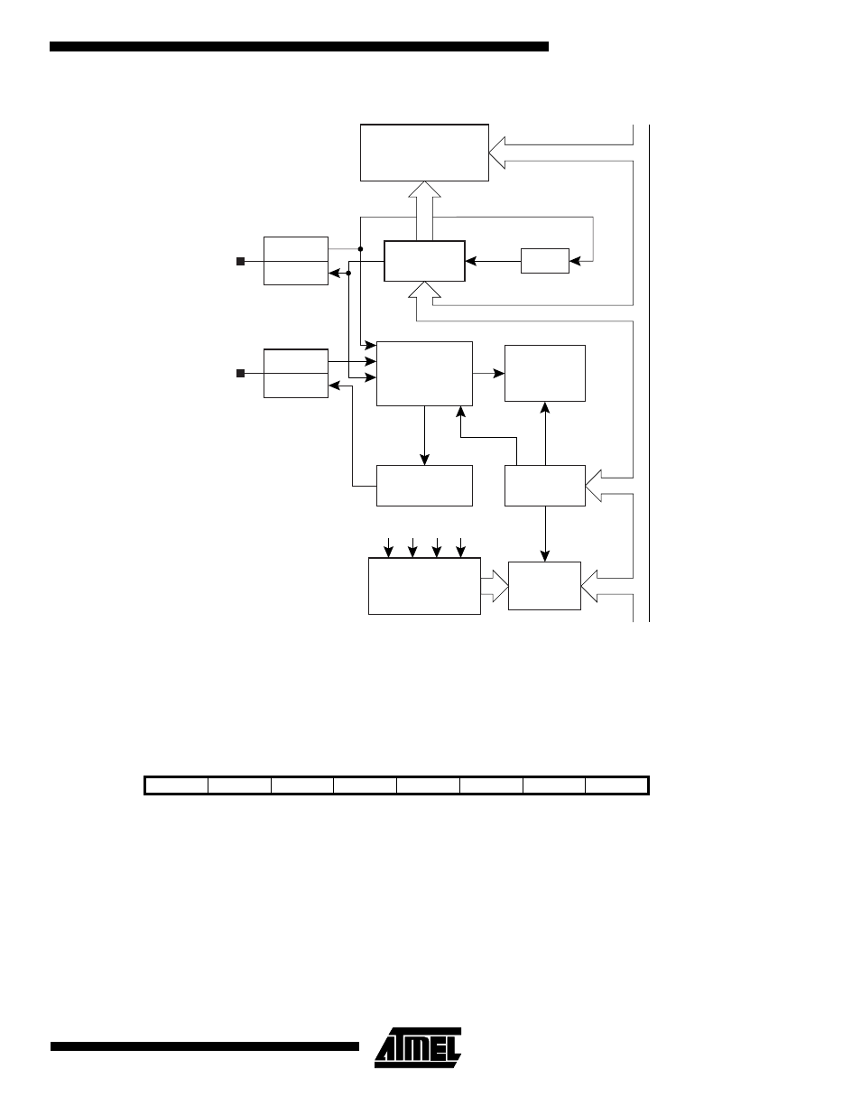
Figure 51. Block diagram of the 2-Wire Serial Interface
The CPU interfaces with the 2-wire Serial Interface via the following five I/O registers: the 2-wire Serial Interface Bit Rate
Register (TWBR), the 2-wire Serial Interface Control Register (TWCR), the 2-wire Serial Interface Status Register (TWSR),
the 2-wire Serial Interface Data Register (TWDR), and the 2-wire Serial Interface Address Register (TWAR, used in slave
mode).
The 2-wire Serial Interface Bit Rate Register - TWBR
•
Bits 7..0 - 2-wire Serial Interface Bit Rate Register
TWBR selects the division factor for the bit rate generator. The bit rate generator is a frequency divider which generates the
SCL clock frequency in the master modes according to the following equation:
• Bit Rate = SCL frequency
• f
CK
= CPU Clock frequency
• TWBR = Contents of the 2-wire Serial Interface Bit Rate Register
• t
A
= Bus alignment adjustion
Bit
7
6
5
4
3
2
1
0
$00 ($20)
TWBR7
TWBR6
TWBR5
TWBR4
TWBR3
TWBR2
TWBR1
TWBR0
TWBR
Read/Write
R/W
R/W
R/W
R/W
R/W
R/W
R/W
R/W
Initial value
0
0
0
0
0
0
0
0
ACK
INPUT
OUTPUT
INPUT
OUTPUT
START/STOP
AND SYNC
ARBITRATION
TIMING
AND
CONTROL
SERIAL CLOCK
GENERATOR
STATE MACHINE
AND
STATUS DECODER
DATA SHIFT
REGISTER
ADDRESS REGISTER
AND
COMPARATOR
TWAR
SDA
SCL
TWDR
CONTROL
REGISTER
STATUS
REGISTER
STATUS
TWCR
TWSR
A
VR 8-BIT D
A
T
A
B
U
S
Bit Rate
f
CK
16
2(TWBR) + t
A
f
CK
+
-----------------------------------------------------------
=