Digital input select] area, Analog in 9-16, 2tr in a – Panasonic WR-DA7 User Manual
Page 183
C h a p t e r 1 2
D A 7 U s e r s ’ G u i d e
12
-
8
12
D-I/O
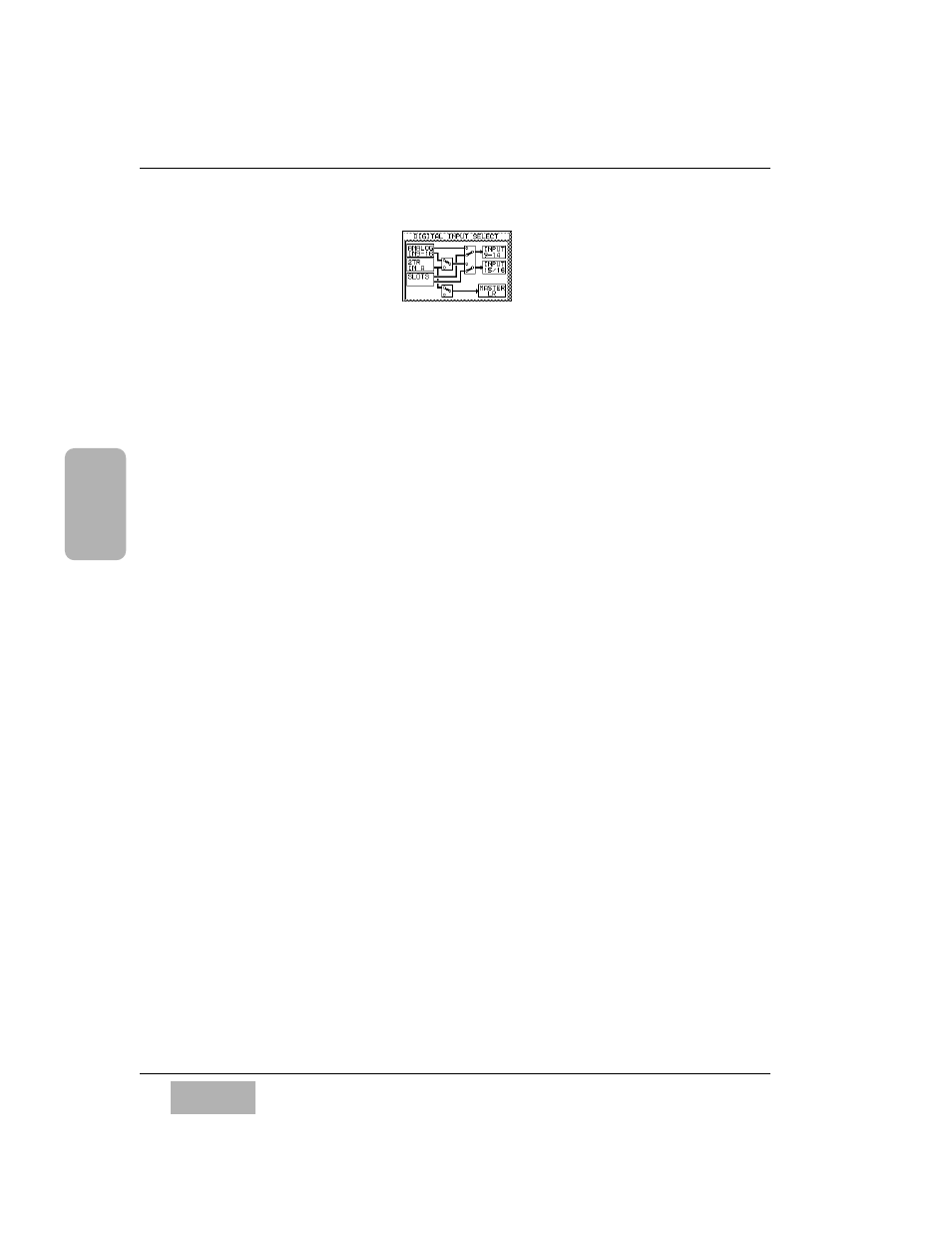
[DIGITAL INPUT SELECT] Area
This area depicts the routing system for digital sources in the DA7. There are
three boxes inside the
[DIGITAL INPUT SELECT] area that are used for
routing the audio signal.
[ANALOG IN 9-16]
This permits assignment of analog inputs 9 through 16 to the inputs 9
through 14 and 15/16. This is the default setting. To select these inputs to be
digital, insert a card in Slot 3, and see instructions under
[SLOT3] in this
section.
For
ANALOG IN 9-16, cursor to the square box to the right of the ANALOG
IN 9-16 and 2TR IN A areas, and press the ENTER button to toggle the
switch into either the up or down position. The up position allows the
ANALOG IN 9-16 audio signals to travel through to INPUTS 9-16. Cursor to
the next box on the right, and again press the
ENTER button to toggle the
switches up or down. In the up position, it completes the routing of
Analog
9-16 to INPUTS 9-14, 15/16.
[2TR IN A]
The
[2 TR A] inputs can be channeled to INPUTS 15/16, MASTER L/R, or
routed directly to
MONITOR A.
To route the
2TR IN A audio signals to INPUT 15/16, cursor to the square
outlined box to the right of the
2TR IN A area, and press the ENTER button
until the switch toggles into the down position. Cursor to the right, and toggle
the next square outlined box to the up position. The audio signal from the
2TR A IN will appear on INPUT 15/16.
The square box near the bottom of the
[DIGITAL INPUT SELECT] area,
when toggled up, will route the
2TR A IN audio signal directly to the
MASTER L/R output. When toggled to the down position, it disconnects the
send to
MASTER L/R.
DIGITAL INPUT SELECT Area