Programming the programmable clock, Programming the programmable clock -43 – Motorola MVME172 User Manual
Page 279
Programming Model
http://www.mcg.mot.com/literature
4-43
4
Programming the Programmable Clock
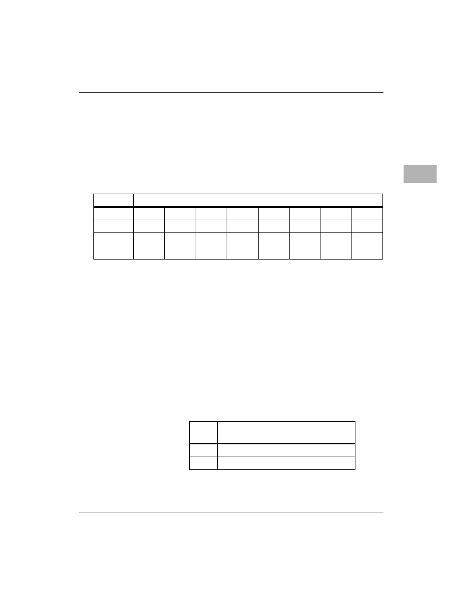
Programmable clock registers are defined in the following paragraphs.
The registers which control IP_c and IP_d are not used on the 200/300-
Series MVME172.
programmable Clock Interrupt Control Register
IL2-0
These three bits select the interrupt level for the
programmable clock interrupt. Level 0 does not generate
an interrupt.
ICLR
Writing a logic 1 to this bit clears the INT status bit. This
bit always reads as 0.
IEN
When IEN is set, the programmable clock interrupt is
enabled. When IEN is cleared, the interrupt is disabled.
INT
When this bit is high, an interrupt is being generated for
the programmable clock at the level programmed in IL2-
IL0.
IRE
This bit controls which action of the programmable clock
output causes interrupts.
ADR/SIZ
$FFFBC080 (8 bits)
BIT
7
6
5
4
3
2
1
0
NAME
0
IRE
INT
IEN
ICLR
IL2
IL1
IL0
OPER
R
R/W
R
R/W
C
R/W
R/W
R/W
RESET
0 R
0 R
0 R
0 R
0 R
0 R
0 R
0 R
IRE
Programmable Clock Action
That Causes Interrupts
0
Rising Edge
1
Falling Edge