Tick timer 2 control register, Tick timer 2 control register -73 – Motorola MVME172 User Manual
Page 151
LCSR Programming Model
http://www.mcg.mot.com/literature
2-73
2
WDCS
When this bit is set high, the watchdog time-out status bit
(WDTO bit in this register) is cleared.
SRST
When this bit is set high, a SYSRESET signal is generated
on the VMEbus. SYSRESET resets the VMEchip2 and
clears this bit.
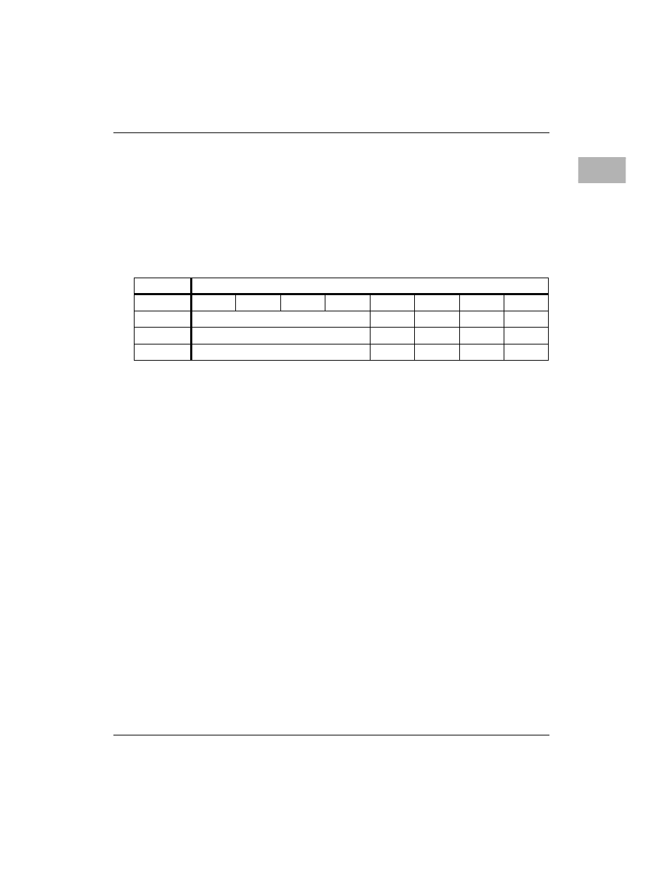
Tick Timer 2 Control Register
EN
When this bit is high, the counter increments. When this
bit is low, the counter does not increment.
COC
When this bit is high, the counter is reset to zero when it
compares with the compare register. When this bit is low,
the counter is not reset.
COVF
The overflow counter is cleared when a one is written to
this bit.
OVF
These bits are the output of the overflow counter. The
overflow counter is incremented each time the tick timer
sends an interrupt to the local bus interrupter. The
overflow counter can be cleared by writing a one to the
COVF bit.
ADR/SIZ
$FFF40060 (8 bits [7 used] of 32)
BIT
15
14
13
12
11
10
9
8
NAME
OVF
COVF
COC
EN
OPER
R
C
R/W
R/W
RESET
0 PS
0 PS
0 PS
0 PS