Motorola MVME172 User Manual
Page 222
3-34
Computer Group Literature Center Web Site
MC2 Chip
3
V10-V8
V10 - V8 are general purpose inputs which are connected
to three jumpers on the MVME172 board. If the bit is set
to a one, the jumper is absent; if it is a zero, the jumper is
present. The jumpers for V10 - V8 are located at J21 pins
5-6, 3-4, 1-2 on the 200/300-Series or J28 pins 11-12, 13-
14, 15-16 on the 400/500-Series (for GPI2, GPI1, and
GPI0, respectively). Refer to your MVME172 installation
and use manual for jumper pin definitions.
V11
Refer to the notes following Table 1-3. 200/300-Series
MVME172 Local Bus Memory Map and Table 1-4.
400/500-Series MVME172 Local Bus Memory Map. The
jumper for V11 is located at J21 pins 7-8 on the 200/300-
Series or J28 pins 9-10 on the 400/500-Series (for GPI3).
Refer to your MVME172 installation and use manual for
jumper pin definitions.
!
Caution
Removing the jumper from J28, pins 9-10, on the 400/500-
Series module will cause the reset code to execute from
EPROM as described in the MVME172 installation and use
manual.
V15-V12
V15 - V12 are general purpose inputs. Refer to the
description for V10 - V8. The jumpers for V15 - V12 are
located at J21 pins 15-16, 13-14, 11-12, 9-10 on the
200/300-Series or J28 pins 1-2, 3-4, 5-6, 7-8 (for GPI7,
GPI6, GPI5, and GPI4, respectively). Refer to your
MVME172 installation and use manual for jumper pin
definitions.
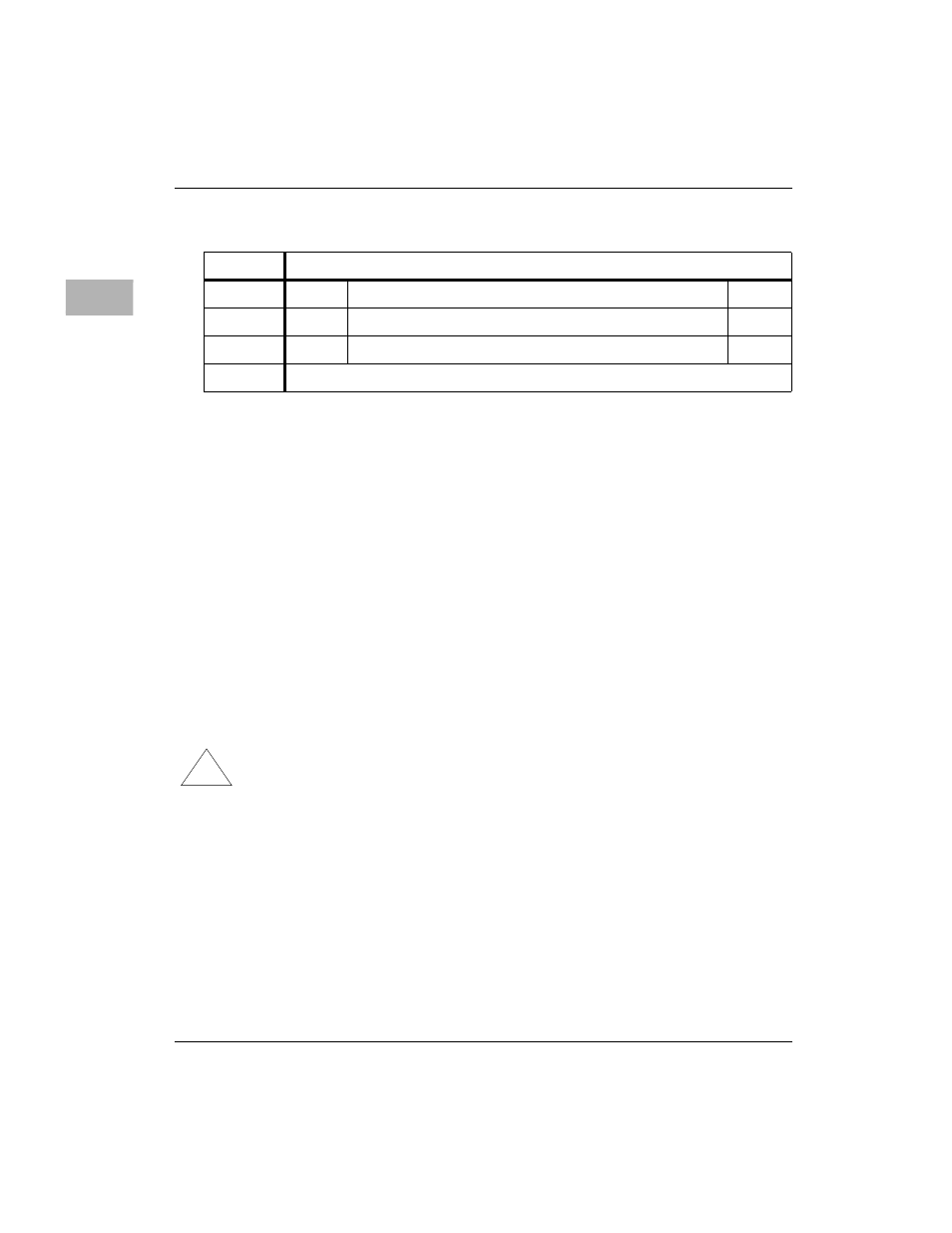
ADR/SIZ
$FFF4202C (8 bits)
BIT
23
22 - 17
16
NAME
V15
V14 - V9
V8
OPER
R
R
R
RESET
Application Specific