3 displays – NewTek TriCaster TC1 (2 RU) User Manual
Page 226
P a g e | 210
22.2.3
DISPLAYS
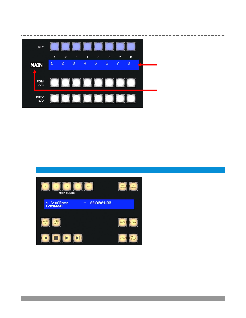
FIGURE 246
Both VMC1 control surfaces feature helpful indicators and system feedback by means of illuminated displays.
1.
An OLED display positioned just left of each stripe normally shows the delegate state for the
associated stripe. For example it may show that the
stripe has been delegated (or ‘assigned’) to
control the Main switcher, one or more M/Es, or for VMC1, one of its supplementary routed output.
2.
The blue LCD panels spanning each stripe just below the
KEY
row show labels identifying the
selection that would result from pressing a button in the same column.
Hint: The numbers 1-24 are silkscreened above the LCD panels as a further aid when making selections.
FIGURE 247
3.
Another LCD strip appears in the
Media Players
group at right in the first (and third, for VMC1 4S)
stripe.
Item 1 above raises the question, “How do I delegate a stripe to control the desired module?” Let’s g
o on to
talk about this, beginning by discussing what “delegating” means in the context
of a control surface.
1. Selection and information
2. Delegate state