3 routing tab – NewTek TriCaster TC1 (2 RU) User Manual
Page 184

P a g e | 168
N
OISE
G
ATE
The
Audio Mixer’s
advanced options panel also include a configurable
Noise Gate
for each audio source, as
well as all outputs. This lets you ensure that unwanted low-level sounds are prevented from inadvertently
intruding into the mix.
A
UTOMATION
Several different per-input automation
features are found in the
Processing
tab.
F
OLLOW
P
ROGRAM
V
IDEO
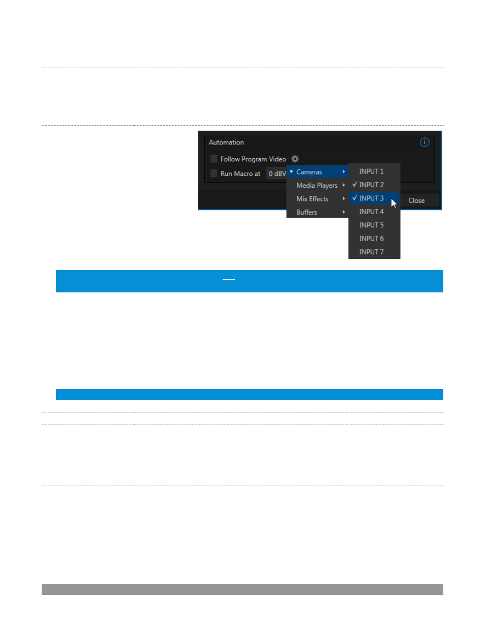
Enabling
Follow
Program
Video
options
for an audio source directs it to track
switcher operations affecting the
related video source.
Audio for sources with
Follow
Program video
enabled in the
Audio Configuration
panel is automatically removed from mixed outputs until one or more specified
video sources are actually displayed on
Program Output
.
Hint: When the corresponding video source is not displayed on output, the
audio source’s
VU meter level is
displayed as a grayscale.
R
UN
M
ACRO AT
The nearby
Run Macro at
(value in dB VU) is part of the
Audio Mixer’s
powerful automation toolset. Click the
E
(Event) button to assign macros to run when the sound level for the input passes the threshold audio level
(transients such as a brief cough are filtered out).
In this manner you could, for example, automatically perform a ‘hands
-
free’ camera switch to show someone
who begins speaking, and then automatically switch back again when he stops.
Note: Not included on some models.
16.10.3
ROUTING TAB
Except on TC Mini, a main tab labeled
Routing
appears in the
Configuration
panel for all sources (Figure 205).
The controls in this group determine output routing of the various channels supplied as inputs to the various
output mix busses (
MASTER, AUX 1
, etc.)
Let’s
discuss what an audio bus is and its uses before proceeding.
B
USSES AND
O
UTPUTS
Consider a very basic audio mixer. Its main audio signal path, from input to output, is properly called the
‘
master bus
.’ Sound su
pplied to one or more inputs is placed on this master bus (in the jargon of audio
processing, this is called a ‘send’), which ultimately flows to output connectors.
Slightly more advanced mixers often provide more than one ‘send’ for individual inputs. F
or example, the
sound from all inputs may be sent to the master bus, comprising the ‘master mix’. A different mix,
sometimes
called a ‘sub
-
mix’, might also be created by sending certain signals to a secondary (‘auxiliary’, or ‘Aux’) bus.
FIGURE 204
