Section 22.2 control schema – NewTek TriCaster TC1 (2 RU) User Manual
Page 224

P a g e | 208
marked) control surface on the channel you choose. Of course the control surface must also be set to the same
channel for successful communication.
The
NewTek Control Surface
utility identifies the channel each control surface is on by a number from 1-8
after the colon in the
Surface: (Channel)
column. Normally, you can simply set the
Local Channel
to match this
value (a ‘bang’ is shown if the channel the surface is set to does not match the
Local Channel
).
If you find it necessary to modify the channel the
control surface
is set to, proceed as follows:
8.
Hold down the *
SHIFT
,
CTRL
and
ALT
buttons on the control surface at the same time for a couple of
seconds to enable channel select mode. The left-most LCD display in the first stripe in the echelon updates
to show channel selections, and a button in the PGM/A row lights to show the current channel. Tap
another button in the row to change the selection.
*For the four-stripe VMC1 L panel, you must repeat this operation in order to match the second
echelon’s channel setting to that of the first. Press and hold the
number pad
buttons labeled 1, 2 and
3
in the third stripe
(rather than
SHIFT
,
CTRL
and
ALT
) in this case; then make your channel selection using
in the a button in the PGM/A row of the third stripe.
With these settings you can, for example, set one system to listen a certain control surface on channel 1, and set
a different unit to listen to the same control surface on channel 2
–
then easily go from controlling one system to
controlling the other by updating the surface channel setting.
SECTION 22.2
CONTROL SCHEMA
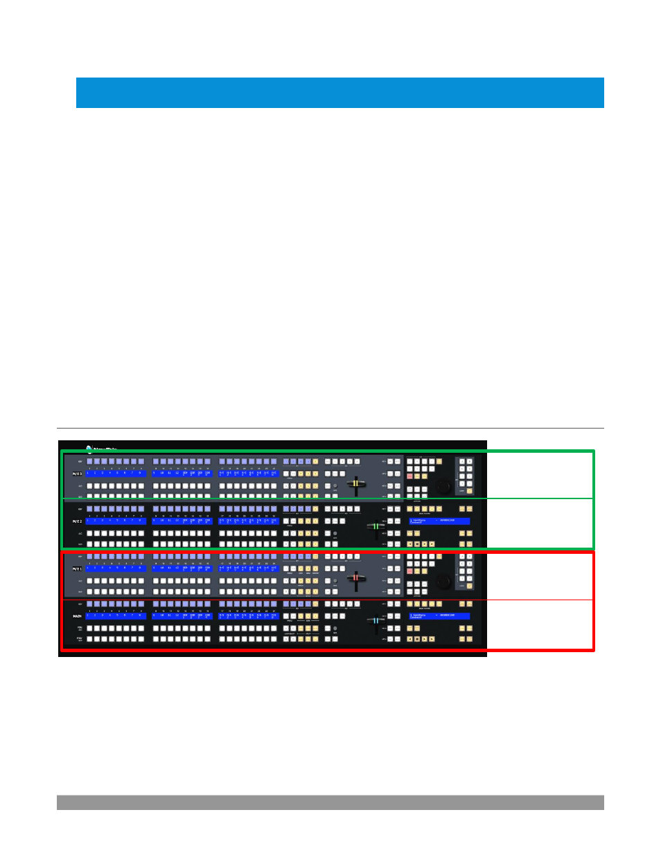
FIGURE 243
Generally, you can think of the various control groups provided as being organized into horizontal ‘stripes’.
In turn, two stripes are paired together in upper and lower echelons, as shown above.
Second Echelon
Stripe 3
Stripe 4
First Echelon
Stripe 1
Stripe 2
