NewTek TriCaster TC1 (2 RU) User Manual
Page 223
P a g e | 207
4.
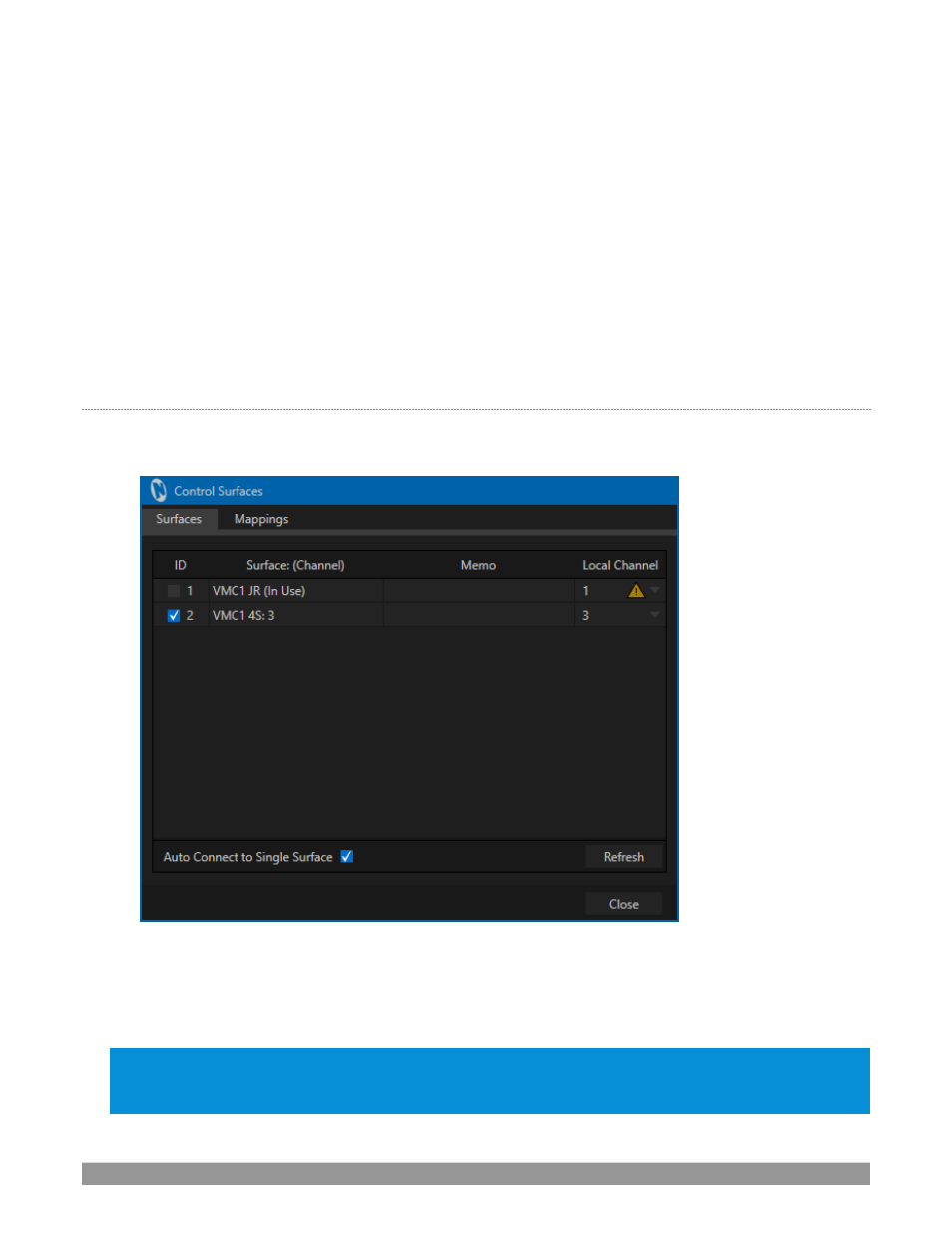
Each surface discovered is listed in a numbered row. The ID number for the row is not permanently
associated with a particular surface, and may change as surfaces are added to or removed from the
network. The ID number does serve a very useful purpose, however.
If you look at the top-left LCD display panel of an un-paired control surface when this utility is open,
its ID number is temporarily shown. This makes it easy to match an entry in the panel with a specific
physical surface.
5.
Once you identify the surface you want to use, simply checkmark it in the list to claim it for the local
system (the steps in the next sub-heading, Setting the Channel, will complete the communication
connection to the surface).
6.
You can also enter a brief description (“BillyBob’s VMC1 4S”) into the
Memo
field, for later reference.
S
ETTING THE
C
HANNEL
7.
Finally, notice that a
Local
Channel
menu is provided for each surface
–
or more accurately, for each
echelon, or
two stripe pair on the surface (see Section 22.2.1
). Let’s discuss this detail a bit further.
FIGURE 242
The
Channel
menu controls just one of two related channel settings
–
this one (on the local host), and another
channel used by the control surface itself. These combine to let you connect to and control alternate live
production systems.
Hint: You might think of the control and system channels as bein
g like the channel settings of two ‘walkie
talkies’ (2
-way radios). For two-way radios to connect, both units must be on the same channel. Similarly, the
channel selection displayed in this software pane tells the local unit to communicate with the selected (check-