Section 9.6 linking switcher rows, Section 9.7 transitions and effects, 1 standard mode – NewTek TriCaster TC1 (2 RU) User Manual
Page 110
P a g e | 94
SECTION 9.6
LINKING SWITCHER ROWS
It can be useful to link two (or more)
Switcher
or
M/E
source rows together, so
cause them to operate synchronously.
Program
and
Preview
rows and
M/E
source rows all show a triangle beside the row label at left. Click it to open a
menu that lets you set up linking.
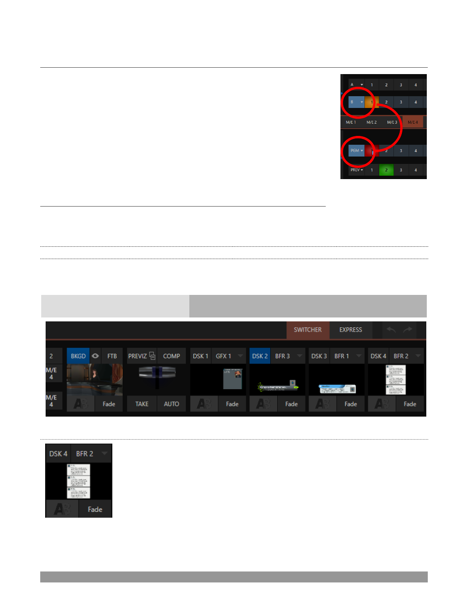
As you’d expect, rows assigned to the same color groups are linked. A selection
made in any linked row updates the selection of all other rows in the same
color group to match. Thus Figure 98 shows the
Input A
row for an
M/E
linked
to the
PGM
row of the main
Switcher
. The
Ungroup
menu item removes the
current row from a group, while
Clear this group
removes all rows from the
current group.
SECTION 9.7
TRANSITIONS AND EFFECTS
We discussed video layers in Section 9.4. With this in mind
, it’s easy to comprehend the
layout and use of
the
Transition
controls. Le
t’s consider the
Transition
controls in the standard
Switcher
layout first.
9.7.1
STANDARD MODE
At left in this group are the main
Transition
controls, including the
T-bar
. The control groups right of the T-
Bar provide configuration and control options for the individual
DSK layers.
Background Layer Transitions
DSK Layer Transitions
FIGURE 99 (TC1 SHOWN)
DSK
C
ONTROLS
FIGURE 100
Each
DSK
layer has a live video viewport showing the current source assigned to it
(using the menu at right above the viewport) and its own transition effect.
Click the transition icon at lower left below the viewport to reveal a palette of
different transition presets (Figure 102) provided for quick selection.
Click an entry in the palette to select it, o
r move the mouse pointer to the “
+
”
sign
that pops up for each icon and click to open the
Custom Media Browser.
FIGURE 98