Network input network output, Mapping the fast fill to output relay #1, Ho0.0 = hi2.1 – Hardy HI 3010 Filler/Dispenser Controller User Manual
Page 91: Network input, Network output
75
CHAPTER 6
Mapping
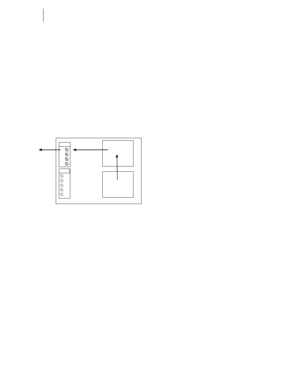
The Destination is Output Relay #1 a State value that is
located in the Output Image Table at Address HO0.0.
The source is the Fast Fill value that is stored in the Fast Fill
memory address (HI2.1) in the Input Image Table. Do not
confuse the value with the address.
So now you have a Destination Address to which you can
assign the Source value.
My Assignment Statement is:
HO0.0 = HI2.1
Output Relay = Fast Fill
FIG. 6-39 MAPPING THE FAST FILL TO OUTPUT
RELAY #1
As the instrument scans the Input Image Table it sees the
new state value (close = 1) for the Fast Fill which was set by
the instrument’s firmware. It takes the new state value (1)
and sends it to the Output Relay #1 address on the Output
Image Table and sets the desired state for the relay to 1
which simultaneously closes the relay that opens the actuator
for a valve to begin a Fast Fill.
Network Input
PLC’s also have Input Image Tables and Output Image
Tables. The HI 3010 is a node in a total network and you
assign the HI 3010 Filler/Dispenser a node address so the
Network scanner can identify the instrument.
WARNING: Y
OU
CANNOT
ASSIGN
THE
SAME
ADDRESS
TO
TWO
DIFFERENT
NODES
. T
HE
PLC
CANNOT
DETERMINE
WHICH
NODE
IT
IS
COMMUNICATING
WITH
. T
HIS
CAN
RESULT
IN
PROPERTY
DAMAGE
OR
PERSONAL
INJURY
.
The Network scanner, scans each node’s Output Image Table
to read the values that are located there. If there are values in
the nodes’ Output Image Table it reads the values to the
PLC’s Input Image Table which makes the data available to
the PLC for processing.
Here again you can assign the data in the node’s output
image table to an address in the PLC input image Table. So if
you want the net weight to be displayed in the PLC’s output
(screen) you have already assigned the Net Weight value
located in the Input Image Table to the Output Image Table.
The PLC Scanner reads the Net Weight value in the nodes’s
Output Image Table and moves the value to a word location
in the Input Image Table on the PLC. The Input Image Table
Net Weight value is then output let’s say to the PLC screen.
Network Output
When the Network Scanner writes values to the nodes it does
this by taking the data located in the PLC Output Image
Table and writes the values to another nodes’ Input Image
Table. Once the value is in the node’s Input Image Table it
becomes a source and can be mapped to any destination in
the HI 3010. (See Fig. 6-40)
Local Mapping - HI 3010
HI 3010
Input Image
Table
Output Image
Table
0
1
2
3
Output
0
1
2
3
4
Input
Fast Fill (HI2.1)
value 1
Output Relay #1
Desired State (1)
HO0.0 = HI2.1
1
2
3
4
To Actuator