Mapping a network input to a local output, Devicenet int out (dio2) set as destination, Process data/selecting gross weight – Hardy HI 3010 Filler/Dispenser Controller User Manual
Page 87: Assignment statement mapping gross, Local output/selecting output relay #2, Output relay #2 (ho0.1) set as destination, Network/selecting devicenet boolean in, Network/selecting non-boolean devicenet
71
CHAPTER 6
Mapping
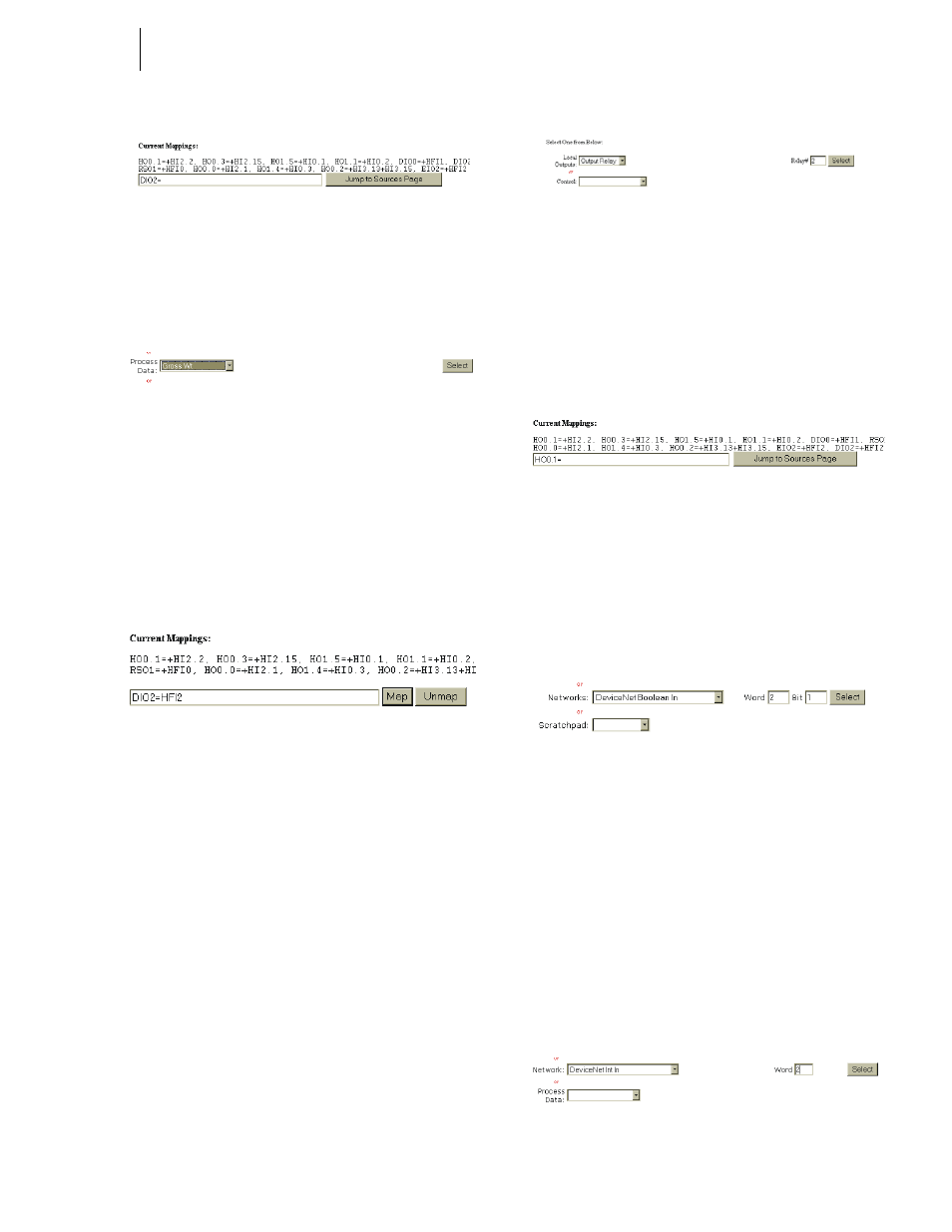
FIG. 6-24 DEVICENET INT OUT (DIO2) SET AS
DESTINATION
Step 4. Click on the “Jump to Sources Page” button. The
Configuration - Mapping #2 page appears.
FIG. 6-25 PROCESS DATA/SELECTING GROSS
WEIGHT
Step 5. Click on the Process Data pull down menu. (See
Fig. 6-25)
Step 6. Click on Gross Wt. (See Fig. 6-25)
Step 7. Click on the Select button to enter Gross Wt as the
source of the Assignment Statement.
Step 8. The Gross Wt address appears on the right side of
the Assignment Statement. (See Fig. 6-26)
FIG. 6-26 ASSIGNMENT STATEMENT MAPPING
GROSS WEIGHT (HF12) TO DEVICENET INT OUT
(DIO2)
Step 9. The Gross Weight is now available to the PLC via
the DeviceNet Scanner.
Mapping a Network Input to a Local Output
If you want a PLC to send instructions to an HI 3010 you
will have to map the local Output to a network input. Here is
the process:
NOTE:
Keep in mind that the network input on the HI
3010 will be the source for the PLC output. This
enables the PLC to send instructions to the net-
work input on the HI 3010 and in turn to the HI
3010 output.
Step 1. From the Configuration - Mapping Setup #1 page,
click on the Local Outputs pull down menu and
select Output Relay. (See Fig. 6-27)
FIG. 6-27 LOCAL OUTPUT/SELECTING OUTPUT
RELAY #2
Step 2. Double click in the Relay# field and type the num-
ber of the relay you want. In our example we
selected Relay #2.
Step 3. Click on the Select button to select Output Relay #2
as the Destination for the left side of the Assign-
ment Statement. (See Fig. 6-28)
FIG. 6-28 OUTPUT RELAY #2 (HO0.1) SET AS
DESTINATION
Step 4. Click on the “Jump to Sources Page” button. The
Configuration - Mapping #2 page appears.
Step 5. Click on the Network pull down menu. (See Fig. 6-
29)
FIG. 6-29 NETWORK/SELECTING DEVICENET
BOOLEAN IN
Step 6. The best choice for a source is a Boolean network
selection. In our example we selected “DeviceNet
Boolean In”. However you can select any of the
Network Sources. When you select a non-Boolean
source you are creating a mixed map. Go to the
Mixed Mapping Section below for more informa-
tion.
Step 7. Double click in the Word text field and put in the
word number. Double click in the Bit text field and
enter the bit number. In our example we selected
Word 2, bit 1. (See Fig. 6-30)
FIG. 6-30 NETWORK/SELECTING NON-BOOLEAN
DEVICENET INT IN