Installing the smart diagnostics (-sd) card, Main controller board installed with rear, Rear plate fasteners – Hardy HI 3010 Filler/Dispenser Controller User Manual
Page 32: Standoff locations
HI-3010 Filler/Dispenser/IBC
16
Service Manual
•
Place the Main Board rear plate so that the
threaded holes on each side of the instrument
chassis are aligned.
•
Screw a panhead screw (#4-40) into the
threaded hole on the instrument chassis. Do
not tighten.
•
Screw the panhead screws that attach the
rear plate to the Main Board until they are
finger tight.
•
Use a Phillips head screw driver and tighten
all the installed screws until snug.
CAUTION: D
O
NOT
OVERTIGHTEN
.
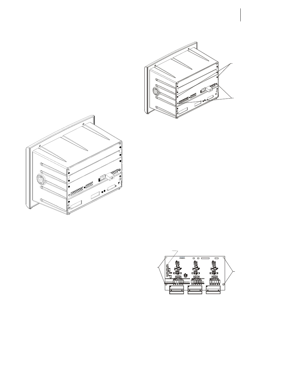
FIG. 3-13 MAIN CONTROLLER BOARD
INSTALLED WITH REAR PLATE
Step 5. Installation of all the PC Boards used in any HI
3000 Series Instrument requires the same proce-
dures.
Installing the Smart Diagnostics (-SD)
Card
NOTE:
For Configuration Instructions go to Chapter 4 -
Options Configuration/Smart Diagnostics Con-
figuration.
Step 1. Unplug the power connector and cable.
Step 2. Remove the Secure Memory Module.
Step 3. Unplug the load cell connector and cable.
Step 4. Disconnect all the communication cables connected
to the instrument.
Step 5. Use a phillips head screw driver and remove the
two phillips head screws that fasten the back plate
to the rear of the instrument chassis. (See Fig. 3-14)
FIG. 3-14 REAR PLATE FASTENERS
Step 6. Grasp the two thumb screws and gently pull the rear
plate and Main Board out of the instrument.
Step 7. Use a phillips head screw driver and remove the
three phillips screws that fasten the rear plate to the
Single Channel Main board.
Step 8. Remove the two thumb screws that fasten the rear
plate to the Single Channel Main board.
Step 9. Attach the four (4) 7/8” standoffs to the Smart
Diagnostics Card with the four (4) 1/4” phillips
screws. Tighten the screws until they are snug. Do
not overtighten. (See Fig. 3-15)
Step 10. With the Hardy Logo facing the back of the Main
board, line up the pins of the Smart Diagnostics
card with the connector on the Main board.
NOTE:
Make sure that none of the pins are bent before
installing.
FIG. 3-15 STANDOFF LOCATIONS
Step 11. Gently push the pins into the connector making sure
that the standoffs are aligned with the standoff holes
in the Main board. When the standoffs are flush
with the Main board.
Step 12. Use a phillips head screw driver and install the four
(4) phillips screws that fasten the main board to the
Thumb
Screws
Phillips
Screws
SMART DIAGNOSTICS PWA
0535-0502-
REV
SN
OPTION
Install
Standoffs
Here
Install
Standoffs
Here
C o n n e c to r P in s
to M a in B o a r d