Simple network mapping, Mapping to a network output, Overfill alarm (hi3.13) entered in the – Hardy HI 3010 Filler/Dispenser Controller User Manual
Page 86: Adding boolean “or” to the assignment, Alarms/selecting slow gate shut alarm, Slow gate shut (hi3.15) added as the second, Multiple source map, Network/selecting devicenet int out
HI-3010 Filler/Dispenser/IBC
70
Service Manual
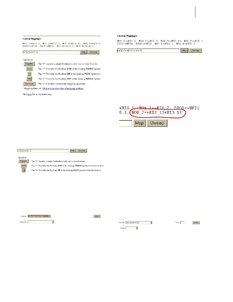
FIG. 6-18 OVERFILL ALARM (HI3.13) ENTERED IN
THE MAPPING ASSIGNMENT STATEMENT
Step 7. To add another Source to the Assignment Statement
and make it a Boolean “or” Statement, click on the
Or button below the Assignment Statement. A “+”
plus sign appears to the right of the Overfill
Address. (See Fig. 6-19)
FIG. 6-19 ADDING BOOLEAN “OR” TO THE
ASSIGNMENT STATEMENT
Step 8. Click on the Alarms pull down menu. (See Fig. 6-
20)
Step 9. Click on Slow Gate Shut Alarm.
FIG. 6-20 ALARMS/SELECTING SLOW GATE SHUT
ALARM
Step 10. Click on the Select button to the right of the Alarms
pull down menu to add the “Slow Gate Shut Alarm”
to the Assignment Statement. (See Fig. 6-21)
FIG. 6-21 SLOW GATE SHUT (HI3.15) ADDED AS
THE SECOND SOURCE TO THE ASSIGNMENT
STATEMENT
Step 11. Click on the Map button to save the mapping. The
multiple source map appears in the Current Map-
pings listing. (See Fig. 6-22)
FIG. 6-22 MULTIPLE SOURCE MAP
Step 12. You have now mapped multiple sources to a single
destination.
Simple Network Mapping
Mapping to a Network Output
If you want to send data to a PLC or other HI 3000 instru-
ment you need to map the data to a network output. Here is
the process:
Step 1. From the Configuration - Mapping Setup #1 page,
click on the Network pull down menu and select
DeviceNet Int Out. (See Fig. 6-23)
FIG. 6-23 NETWORK/SELECTING DEVICENET INT
OUT
Step 2. Double click in the Word text box and type in the
number 2.
Step 3. Click on the Select button to set the Destination.
The DeviceNet Int Out address appears on the left
side of the Assignment Statement. (See Fig. 6-24)