Ethernet parameters, About the ethernet parameters about ip addresses, Devicenet menu/node address – Hardy HI 3010 Filler/Dispenser Controller User Manual
Page 61: Setup menu/ethernet, Ethernet menu/ip address with default
45
CHAPTER 4
Configuration
NOTE:
Check with your Network Administrator for the
Baud Rate if you don’t know the correct Baud
Rate.
Step 4. Press the Enter button to set the entry.
Step 5. Press the Down arrow until the cursor is in front of
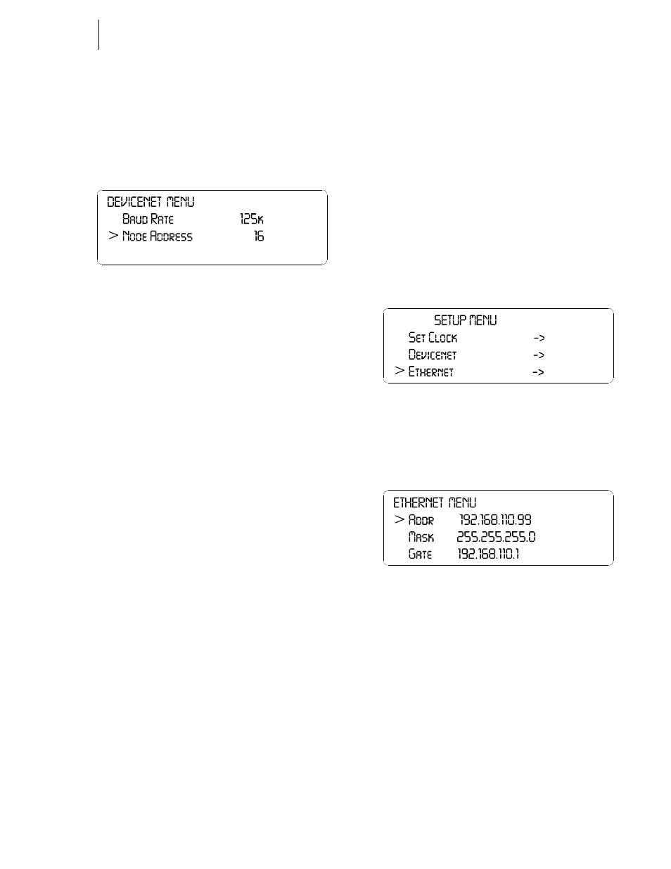
Node Address. (See Fig. 4-93)
FIG. 4-93 DEVICENET MENU/NODE ADDRESS
Step 6. Press the right or left arrow buttons to select the
Node Address.
Step 7. Press the Enter button to set the entry.
Step 8. Press the Exit button to return to the SETUP
MENU.
Ethernet Parameters
About the Ethernet Parameters
All Filler/Dispensers are designed with a selectable 10/100
base T Ethernet connection which links your PC to an
embedded server in the instrument. You can connect to an
instrument via the Internet, Intranet, Extranet, or VPN (Vir-
tual Private Network). Your computer must have an ethernet
card and cable with an RJ45 connector to connect to the
instrument. Once connected you can transfer data, monitor,
map and configure any of the instruments from your web
browser from any location in your plant or enterprise. Help
Dialogs are also available to assist when performing setup or
troubleshooting of an instrument. In addition the browser
connects you to the Hardy Web Site which connects the user
to a full range of customer service and support. File down-
loads from your control room are a snap. No more hauling
devices to download files to an instrument. Should you want
to download a file or monitor the instrument from your lap-
top at the site, simply connect a short cable from the lap top
to the Ethernet connect at the rear panel of the instrument to
transfer files, monitor or configure the instrument. No matter
where you are, if you are connected to our instrument you
can configure and troubleshoot the HI 3010 Filler/Dispenser.
About IP Addresses
An IP address consists of 32 bits. It is composed of two
parts:
•
The Network Number
•
The Host Number
By convention, the address is expressed as four decimal
numbers separated by periods, such as “200.1.2.3” represent-
ing the decimal value of each of the four bytes. Valid
addresses thus range from 0.0.0.0 to 255.255.255.255, a total
of about 4.3 billion addresses.
It is recommended that you leave the Mask, Gate and DNS
settings alone. Contact your Network Administrator if you
need to set these parameters.
PARAMETER:ETHERNET
RANGE: 0.0.0.0 - 255.255.255.255
DEFAULT: 192.168.110.1
Step 1. Press the Down arrow button until the cursor is in
front of Ethernet. (See Fig. 4-94)
FIG. 4-94 SETUP MENU/ETHERNET
Step 2. Press the Enter button. The Ethernet Menu appears
with the cursor in front of the IP Address. (See Fig.
4-95)
FIG. 4-95 ETHERNET MENU/IP ADDRESS WITH
DEFAULT IP ADDRESS
Step 3. Press the Clear button to clear the address.
NOTE:
Figure 4-96 has the Default IP address. You must
change this address when starting the instrument
for the first time.
Step 4. Use the alphanumeric key pad to enter the new
address. Remember there must be a period between
each port of the address. (e.g. 186.245.263.12)
Step 5. This is the only parameter you need to change. If
you need to change the other parameters, contact
your Network Administrator for assistance.
Step 6. Press the Enter button to set the entry.
Step 7. Press the Exit button to return to the SETUP
MENU.