J - electrical inspection – Hardy HI 3010 Filler/Dispenser Controller User Manual
Page 124
HI-3010 Filler/Dispenser/IBC
108
Service Manual
J - Electrical Inspection
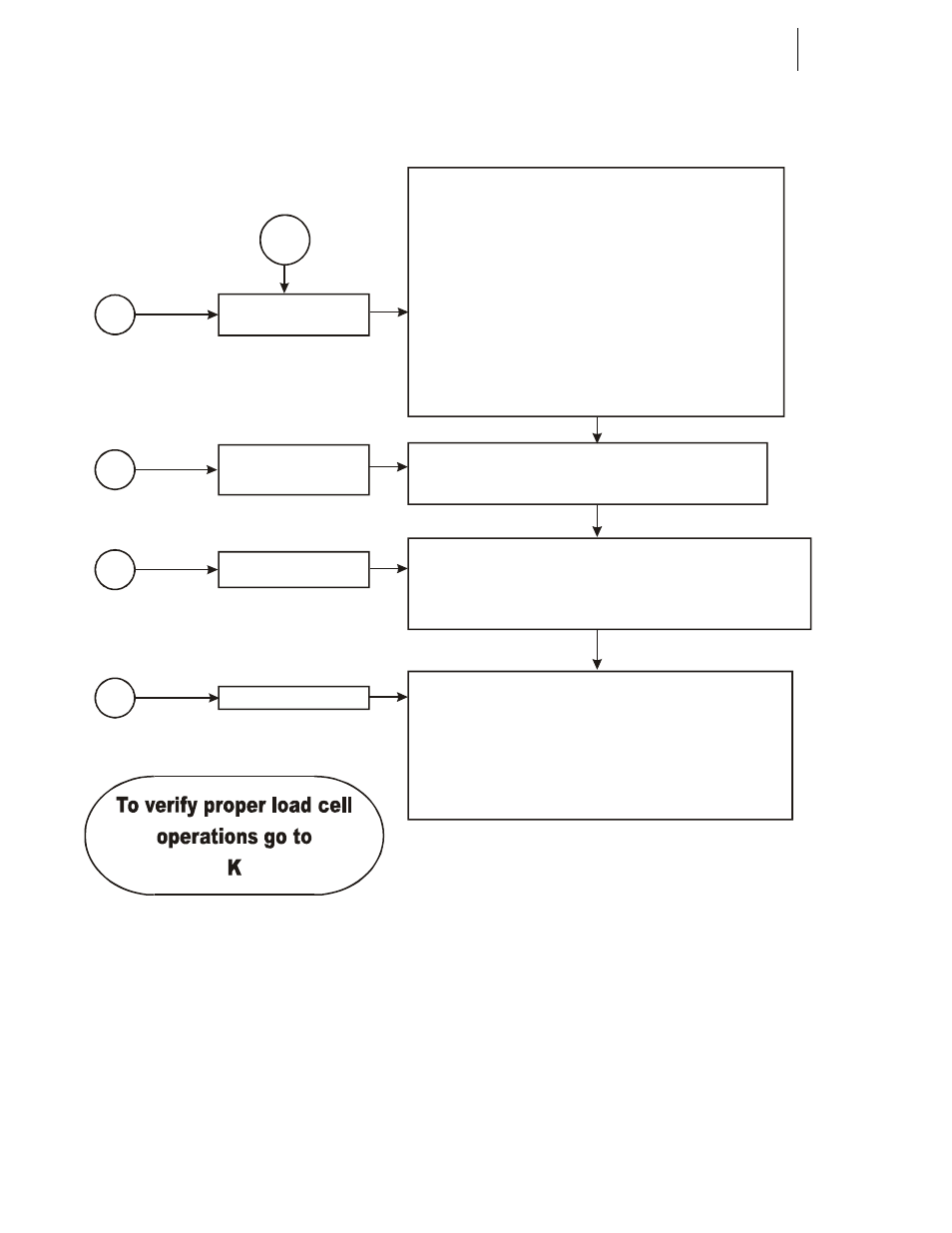
J
J1
1) Verify the front display illuminates.
2) Completes the Initialization process.
3) Displays a weight reading. This weight value will not be
correct if a calibration procedures were not performed.
Apply weight to the vessel
a) Does the weight increase and decrease in the
correct direction with the weight?
B) Is the weight reading repeatable?
C) The weight value will not be correct until a proper
calibration is completed.
1) Verify color code, input is excitation, Output is signal.
2) Shielding
a) Grounded only at the controller
b) Continuous shield connection from the load cell cable
to the instrument. Single point EMI/RFI drain.
c) Terminated but not grounded, at the summing box.
3) Sense lines Installed?
A) Jumpers or sense lines in the J1 connector?
B) Sense lines must be installed for C2 calibration.
4) Using a multimeter verify readings.
Verify the proper
voltage level has been
supplied.
J2
Apply power to the
controller only if supply
voltage is correct.
J3
Does the scale reflect
a weight change?
J4
Cabling
DO NOT POWER UP THE CONTROLLER UNTIL
INPUT VOLTAGES CAN BE VERIFIED!
1) Check the specification label attached to the weight controller
chassis. (110 VAC/220 VAC or 24 VDC)
2) Use a meter to verify neutral, ground and Hot are proper.
3) Computer grade power
4) Use active filters for motor noises and spikes.
5) Use isolation transformers to combat surges and sags.
6) Isolated from SCR and motor control circuits
7) Use a common earth ground.
a) Keep ground cable runs as short as possible
b) Excessive ground cable runs can act as an antenna
for AC noise.
c) Install grounding straps around load cells to direct
static away from the load cell and directly to ground.
d) Install ground straps on the input and discharge
piping, and the vessel to a common earth ground