K - load sharing and load sensor checkout, 109 chapter 7 troubleshooting – Hardy HI 3010 Filler/Dispenser Controller User Manual
Page 125
109
CHAPTER 7
Troubleshooting
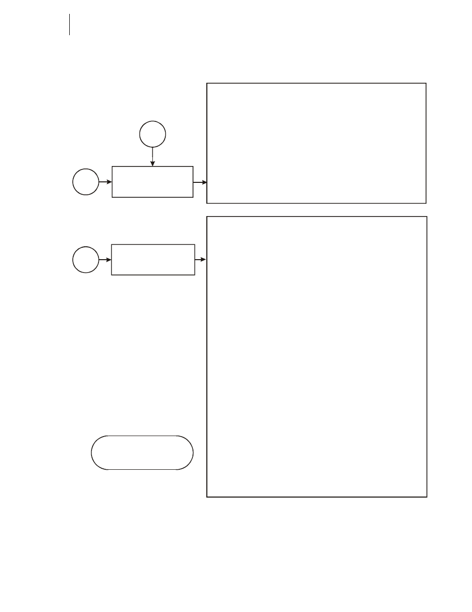
K - Load Sharing and Load Sensor Checkout
Monitor system for proper
operation
Check out complete
K
Verify the proper
voltage level has been
supplied
K1
A pply power to the
controller only if supply
voltage is correct.
K2
1) Does the mV signal increase in a positive
direction?
2) If you receive a negative result, check if load cell
is mounted correctly.
a) The arrow goes with the direction of the force.
b) If there isn’t an arrow, you must manually verify the
correct direction. A negative reading indicates the
load cell is upside down.
c) Load cells in tension will not reflect a negative reading
if installed upside down. If upside down, only the
force applied by the cable would be included in the
weight readings.
D) If you are still receiving a negative signal, verify the
Load cell wire color code.
1) Verify a positive reading from each load cell, using a multi
meter.
2) Record the mV reading and compare each corner for proper load
sharing.
a) Proper load sharing should see only a difference of +/- .5 mV.
b) Larger differences due to motors and piping, should not
exceed +/- 4 mV.
c) If there aren’t any motors, valves or piping to explain the mV
difference, adjust the corners and balance the MV readings.
D) Use shims or if equipped adjusting bolts on the load cell
Mounting Hardware.
E) Drawing a load cell map will help determine the correct
leg to adjust and in which direction.
Three Load Cells Balance Like a Three Legged Chair
1) Using a spirit level, verify the vessel is vertically and horizontally
correct.
2) Verify if any height change effects the attitude of adjacent
vessels or piping.
3) Adjust each leg to dynamically match mV outputs.
4) Verify the mV readings and physical level when complete.
Four Load Cells or More Present a Challenge
1) Use a multi meter:
Determine the sum of the load cell signals and
Your target mV setting for each load cell.
2) Read the output of individual load cells.
3) Adjust the load cell with the lowest reading to dynamically
match the target mV readings obtained in step 1.
4) Read the mV readings from each load cell to verify proper
correction.
5) Repeat steps 3 and 4 to achieve a proper load sharing vessel.
6) Verify the mV readings and vessel level when complete.