Smart diagnostics, Using smart diagnostics from the front panel, Factory defaults set/select application type - 127 – Hardy HI 3010 Filler/Dispenser Controller User Manual
Page 144: 1 test and data menu/selecting diagnostics, Smart diagnostics display/selecting, 3 total millivolt reading
HI-3010 Filler/Dispenser/IBC
128
Service Manual
ADDRESS
,
EVERYTHING
.
THE
INSTRUMENT
IS
RETURNED
TO
THE
CONDITION
IT
WAS
RIGHT
FROM
THE
FACTORY
.
Step 3.
Enter the High Security Code Number.
Step 4.
Click on the Return to Factory Defaults button.
Step 5.
The Confirmation Page appears. (See Fig. 7-100)
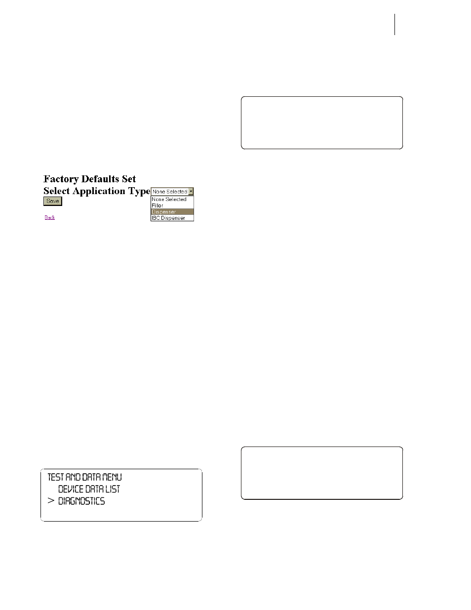
The page informs you that all Factory default
have been set and asks you to select what type of
instrument you want this instrument to be.
Step 6.
Click on the pull down menu and select the type
of instrument you want this instrument to be.
FIG. 7-100 FACTORY DEFAULTS SET/SELECT
APPLICATION TYPE
NOTE:
This procedure is useful when you want to con-
vert the instrument from a filler to a dispenser or
IBC dispenser and vice versa.
Step 7.
Click on the Save button to set the factory
defaults for the application you selected.
Step 8.
Click on “Back” to return to the previous page.
The previous page appears.
Step 9.
Click on the left arrow to return to the Operation
Diagnostics page.
Step 10. Click on Home to return to the Filler/Dispenser
Home Page.
Smart Diagnostics
Using Smart Diagnostics From the Front Panel
Step 1. Press the Test/9 button. The Test and Data Menu
appears. (See Fig. 7-101)
FIG. 7-101 TEST AND DATA MENU/SELECTING
DIAGNOSTICS
Step 2. Press the down arrow until the cursor is in front of
Diagnostics. (See Fig. 7-102)
Step 3. Press the Enter button. The Smart Diagnostics Dis-
play appears with the cursor in front of Voltage &
Weight. (See Fig. 7-103)
FIG. 7-102 SMART DIAGNOSTICS DISPLAY/
SELECTING VOLTAGE & WEIGHT
Step 4. Smart Diagnostics enables you to read total or indi-
vidual load sensor’s Millivolt, Millivolt/Volt or
Weight Reading.
•
The mV reading is a coarser reading than
the mV/V or Weight. The mV reading is
sufficient to balance the corners of your
scale or vessel.
•
These readings allow you to determine if
the problem is in the instrument (internal)
or in a load sensor(s) (external). The speci-
fication range for the instrument is 0-15
mV. If you are getting a reading outside
this range (15.5 mV, 3.1 mV/V Maximum
or any negative values) the problem is
exterior to the Instrument (most likely
improper wiring). If you are getting a read-
ing between 0-15 mV the reading is nor-
mal.
Step 5. To view the total Millivolt readings for all the load
sensors that are connected to the scale, press the up
or down arrow buttons until the cursor is in front
Voltage & Weight.
Step 6. Press the Enter button. The total millivolt reading
for the scale appears. (See Fig. 103)
FIG. 7-103 TOTAL MILLIVOLT READING
NOTE:
The values listed here are for illustration pur-
poses only. Your readings will be different.
Step 7. To view individual millivolt readings for individual
load cells:
>
SMART DIAGNOSTICS
Voltage & Weight - >
Stabil ity Test - >
Factor y Def aults - >
>
VOLTAGE & WEIGHT
ALL 12.0 Mv - >
ALL 3.0 mV/ V - >
ALL 72.0 l b - >