Diagnostics, Voltage & weight displays, Load sensor display/serial number – Hardy HI 3010 Filler/Dispenser Controller User Manual
Page 137: Ensitivity - input resistance - output, Test data display/load sensor - ip address, Test and data menu
121
CHAPTER 7
Troubleshooting
•
Number of Sensors - The number of sen-
sors detected by the instrument in the Fill-
ing/Dispensing system.
1.
Load Sensor -The instrument will
read C2 load sensors certification
information only.
2.
The instrument displays sensor num-
ber 1 as a default.
3.
If you want to look at the certified
specifications for other load sensors
press the up or down arrows to move
the list of sensors. The instrument can
detect a maximum of 8 sensors.
4.
To view the certified sensor informa-
tion which is read from the C2 chip,
do the following:
a.
Press the Enter button. The Load
Sensor Display appears. (See Fig.
7-67)
FIG. 7-67 LOAD SENSOR DISPLAY/SERIAL NUM-
BER - CAPACITY - SENSITIVITY (MV/V)
b.
Serial Number - This is the serial
number of the selected load sen-
sor.
c.
Capacity - the maximum weigh-
ing capacity of the load sensor.
d.
Sensitivity - Sensitivity specifica-
tion of the load sensor set at the
factory.
e.
Press the down arrow until the
remainder of the load sensor
specifications appear. (See Fig. 7-
68)
FIG. 7-68 SENSITIVITY - INPUT RESISTANCE -
OUTPUT RESISTANCE
f.
Input Resistance - This is the
Certified Input Resistance from
the certification done by the fac-
tory.
g.
This is the Certified Output
Resistance from the certification
done by the factory.
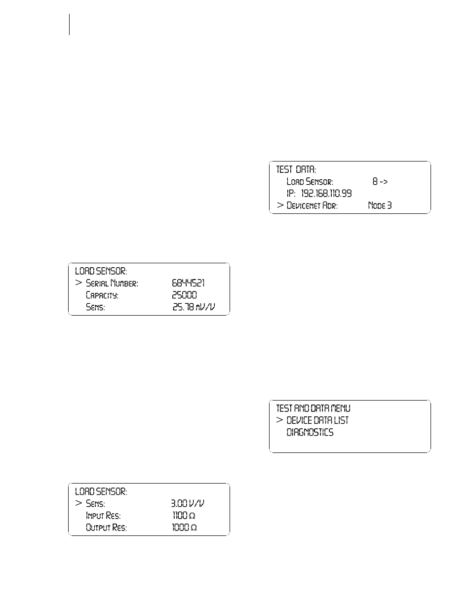
Step 52. Press the down arrow button until the next three
menu items are displayed. (See Fig. 7-69)
FIG. 7-69 TEST DATA DISPLAY/LOAD SENSOR - IP
ADDRESS - DEVICENET ADR
Step 53. IP Address - Devicenet Address are read only.
•
IP - Lists the IP address for this instru-
ment. The address listed in Fig. 5-69 is the
default IP address of an instrument right
from the factory.
•
Devicenet Address - Lists the address of
the Node Address of the instrument you
are checking.
Step 54. Press the Exit button to return to the Test Data Dis-
play.
Step 55. Press the Exit button to return to the Test and Data
Menu. (See Fig.7-70)
FIG. 7-70 TEST AND DATA MENU
Diagnostics
Voltage & Weight Displays
Step 1. Press the down arrow until the cursor is in front of
Diagnostics. (See Fig. 7-71)