Installing printed circuit boards, Filler/dispenser installing in a swivel, Filler/dispenser installed in a swivel – Hardy HI 3010 Filler/Dispenser Controller User Manual
Page 31: Main controller board installation/lining up, Main controller board installation/sliding
15
CHAPTER 3
Installation
NOTE:
When wall mounted, the unit should support a 14
pound weight for one minute without coming
loose or damaging the equipment.
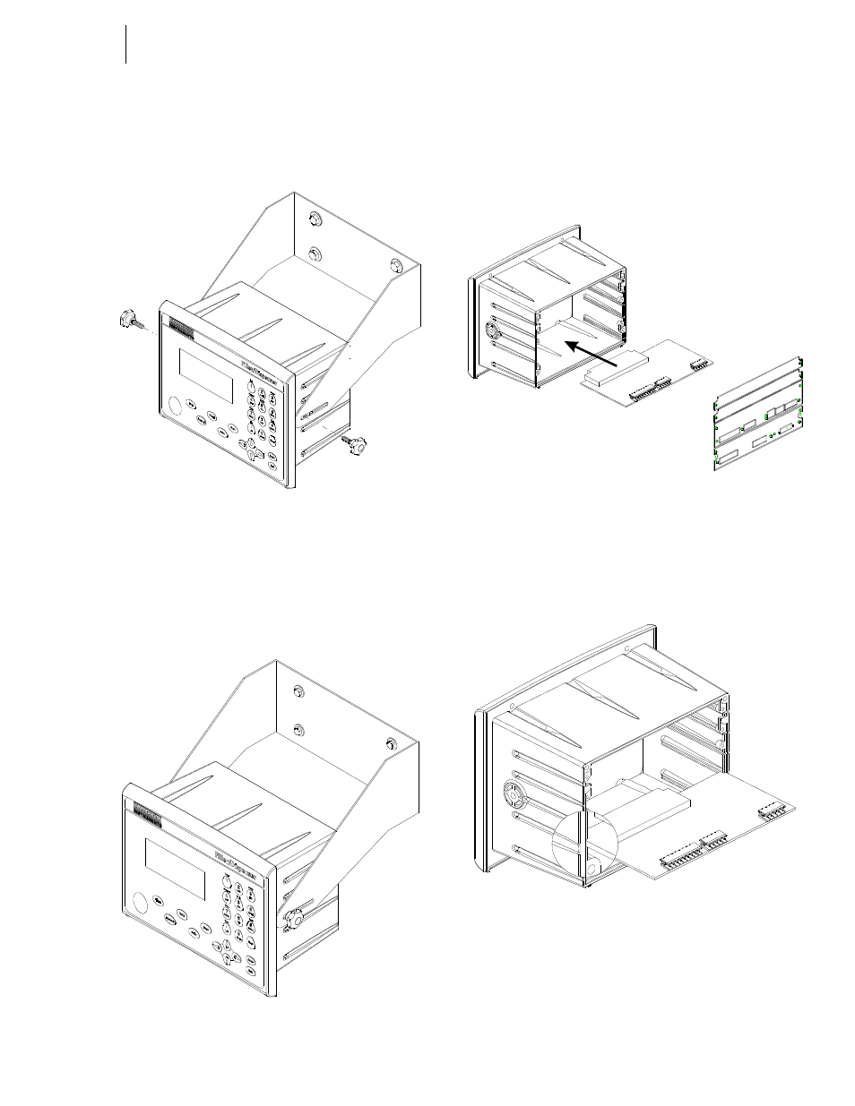
FIG. 3-9 FILLER/DISPENSER INSTALLING IN A
SWIVEL WALL MOUNT
Step 9. Screw the two fastener knobs into the threaded
holes on each side of the Filler/Dispenser until the
brackets are snug against the instrument. (See Figs.
3-9 & 3-10)
FIG. 3-10 FILLER/DISPENSER INSTALLED IN A
SWIVEL/WALL MOUNT
Installing Printed Circuit Boards
Step 1. From the back of the instrument, align the PCB
board with the housing slots in the instrument so
that the backplane connector is facing the instru-
ment. (See Fig. 3-11)
FIG. 3-11 MAIN CONTROLLER BOARD INSTALLA-
TION/LINING UP BOARDS WITH THE SLOTS
Step 2. Gently slide the circuit board into the slots making
sure that the each side of the PC board is in the
proper slot. (See Fig. 3-12)
FIG. 3-12 MAIN CONTROLLER BOARD INSTALLA-
TION/SLIDING THE BOARD INTO THE INSTRU-
MENT
Step 3. Gently push the PC board all the way into the
instrument until the backplane connector is con-
nected to the backplane.
Step 4. Install the Main Board rear plate. (See Fig. 3-13)