Parameters for position control, Connections and settings in position control mode, Standard default setup – Panasonic MINAS E-series User Manual
Page 95
95
[Connections and Settings in Position Control Mode]
Connections and
Settings in Position
Control Mode
PrNo.
Parameter Name
Unit
Function/Content
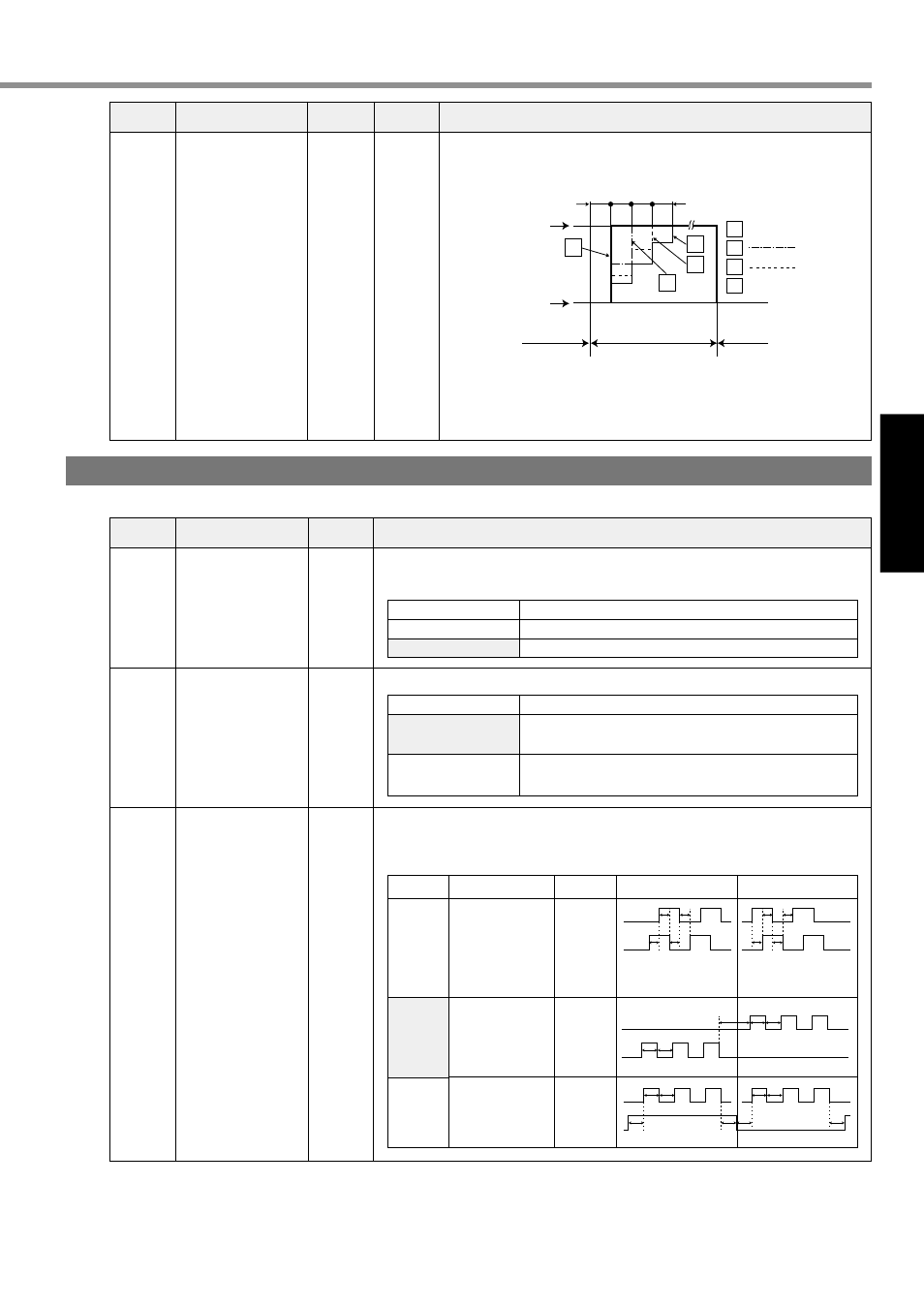
• With the 2nd gain switching function enabled, you can provide
phased switching time only for position loop gain when gain is
switched.
• Switching time is only provided when a small position loop gain is
switched to a large position loop gain (Kp1
→ Kp2) (in order to
alleviate impact to the machine due to abrupt change in gain).
• Set a value that is smaller than a difference between Kp2 and Kp1.
35
Position loop gain
switching time
0 - 10000
[20]*
(Setting value+1)
x 166 ms
Pr35=
Kp2(Pr10)
166
166
166
166
µs
Kp1(Pr18)
1st gain
(Example)
2nd gain
Thick solid line
Thin solid line
1st gain
0
0
1
1
2
2
3
3
Kp1(Pr10) Parameters for Position Control Standard Default Setup: [ ] PrNo. Parameter Name Function/Content The parameter sets a multiplier number with Pr42 (Command pulse input mode set-up) when “2 phase pulse input” is selected as a form of command pulse. The parameter sets direction of rotation of the motor to the command pulse input. The parameter sets input form of command pulse to be given to the driver from the host. Three input forms illustrated in the following table can be set. Select any of them according to specifications of the host. 40 41 42 Command pulse multiplier set-up Command pulse direction of rotation set-up Command pulse input mode set-up 1 - 4 0 - 3 0 - 3 Range of Settings Range of Settings Settings 1 or 2 3 or [4] Multiplier number at 2 phase pulse input x 2 x 4 Settings [0] or 3 1 or 2 Direction of Rotation The motor rotates in a direction given by the command pulse. The motor rotates in a direction opposite to the command pulse. Settings 0 or 2 [1] 3 Signal Name PULS SIGN PULS SIGN PULS SIGN Command pulse form 90˚ phase difference 2 phase pulse (Phase A + Phase B) CW pulse row + CCW pulse row Pulse row + Sign CCW Command CW Command t1 t1 t1 t1 t1 t1 t1 t1 t4 “H” “L” t5 t4 t6 t6 t6 t6 t5 Phase A Phase B Phase B delays from Phase A by 90˚. Phase B goes ahead of Phase A by 90˚. t2 t2 t2 t3 t2