Preparations, Points in wiring wiring diagram – Panasonic MINAS E-series User Manual
Page 29
29
[Preparations]
Preparations
Wiring to Connector CN X4 (Connection with Encoder)
Points in Wiring
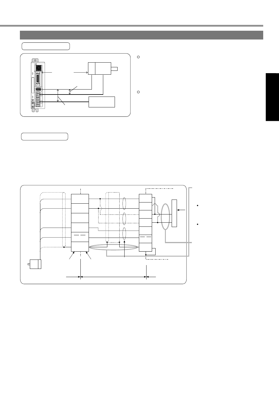
Wiring Diagram
¥ When you plan to make an encoder junction cable by yourself, refer to Requests on a self-made encoder junction
cable (For connectors, refer to Optional Parts (Connector Kits for Connection of Motor and Encoder) on Page
186 of Reference edition).
(1) Refer to the wiring diagram below.
(2) Cable used: Shielded twist pair cable of 0.18 mm
2
(AWG 24) minimum in conductor diameter that is excellent in
bending resistance.
(3) For signal/power wiring in pair,
use twist pair cable.
(4) Shielding treatment
Driver-side shield sheath:
Connect to CNX4 connector
case (FG).
Motor-side shield sheath:
Connect to 6 pins.
(5) Where the cable length
exceeds 10 m, do double-
wiring for the encoder power
(+5V, 0V), as illustrated left.
(6) Connect nothing to the empty
terminal (NC) of the
connector.
Servo motor
2
0V
+5V
1
4
5
3
6
Case
5
4
1
2
3
6
Twist pair
Junction cable
(made by Tyco Electronics AMP K.K.)
172160-1
172168-1
(made by Tyco
Electronics AMP K.K.)
Motor side
Servo driver side
White
Light blue
Purple
Shielded
cable
Black
Regulator
0V
+5V
0V
+5V
TX/RX
TX/RX
FG
0V
+5V
(NC)
TX/RX
TX/RX
FG
X4
CN
(7) Don’t use a cable pair composed of the motor cable and encoder cable which were shielded in batch.
Cable length between the driver and the motor - 20 m max.
If this cable length exceeds 20 m, consult with the
dealer/distributor from which you have purchased the
driver.
Keep 30 cm or more spacing from the main circuit wiring.
Neither guide this wiring through the same duct, together
with the main circuit nor bundle these two together.
x
1
x
3
x
4
x
5
x
6
STATUS
ALM CODE
Power
section
Motor
Encoder
30 cm min.
30 cm min.
20 m max.