Parameter setting – Panasonic MINAS E-series User Manual
Page 118
118
Parameter Setting
PrNo.
Parameter Name
Function/Content
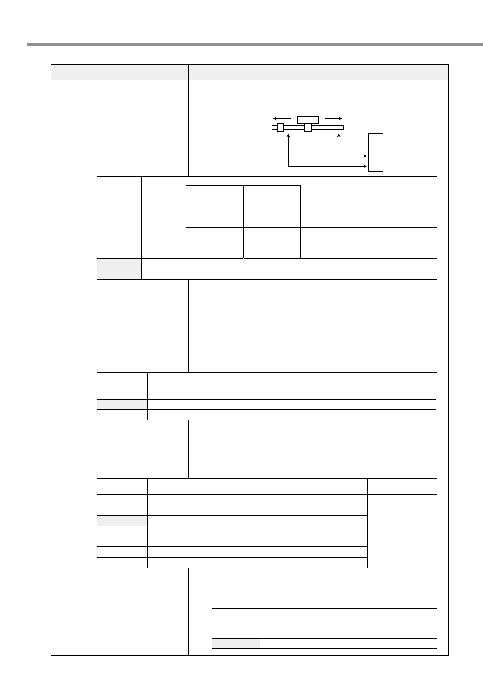
In the case of linear driving, in particular, limit switches should be provided on
both ends of the axis, as illustrated in the figure below, to prevent any mechanical
damage due to overshoot of a work, and inhibit driving in the direction in which
the switches operate.
will be judged as abnormality in which limits are simultaneously exceeded in both
CCW and CW directions, and the driver will trip due to “overtravel input error”.
2. You can set whether to activate a dynamic brake during deceleration when
CCW overtravel inhibit input (CCWL) or CW overtravel inhibit input (CWL)
works. For details, refer to descriptions on Pr66 (Deceleration and stop set-up
at overtravel inhibit).
The parameter is used to select functions of speed zero clamp input (ZEROSPD)/
torque limit switching (TC) input (connector) CN X5 pin 5.
all at once. If settings of Pr70 and Pr73 remain 0, the error No.26 acceleration
protection will occur.
This parameter is to allocate functions of warning output(WARN:CN X5 pin 12).
If you ignore output of warning and continue to use, the motor or driver may fail/
be damaged.
04
06
09
0C
Overtravel Input
inhibit
ZEROSPD/TC input
selection
Warning output
selection
Baud rate set-up of
RS232C
0 - 1
0 - 2
0 - 6
0 - 2
CW Direction
CCW Direction
CCWL
CWL
Work
Servo Motor
Limit
Switch
Limit
Switch
Driver
Standard Default Setup: [ ]
Range of
Settings
Settings
0
[1]
CCWL/
CWLInput
Enabled
Disabled
Input
CCWL
(CN pin X5-8)
CWL
(CN pin X5-7)
Operation
This shows normal state in which the limit
switch on CCW side does not operate.
CCW direction inhibited, and CW direction allowed.
This shows normal state in which the limit
switch on CCW side does not operate.
CW direction inhibited, and CCW direction allowed.
Connection with COM-
Connected
Open
Connected
Open
CCWL and CWL inputs are ignored, and driving is not inhibited (allowed) in both
CCW and CW directions.
Settings
0
1
[2]
Baud Rate
2400bps
4800bps
9600bps
Setting
0
[1]
2
Speed Zero Clamp
Disabled
Enabled
Disabled
Torque Limit Switching Input
Disabled
Disabled
Enabled
Remarks
For detailed
information on
functions of
respective outputs
listed in the left, refer
to “Wiring to
Connector CN X5” on
Page 109.
Functions
Output during torque limit
Zero speed detection output
Over-excessive regeneration/overload/fan rotation speed abnormality
Over-excessive regeneration warning output
Overload warning output
To be displayed, but not functioning.
Fan rotation speed abnormality warning output
Setting
0
1
[2]
3
4
5
6