Connections and settings in position control mode – Panasonic MINAS E-series User Manual
Page 71
71
[Connections and Settings in Position Control Mode]
Connections and
Settings in Position
Control Mode
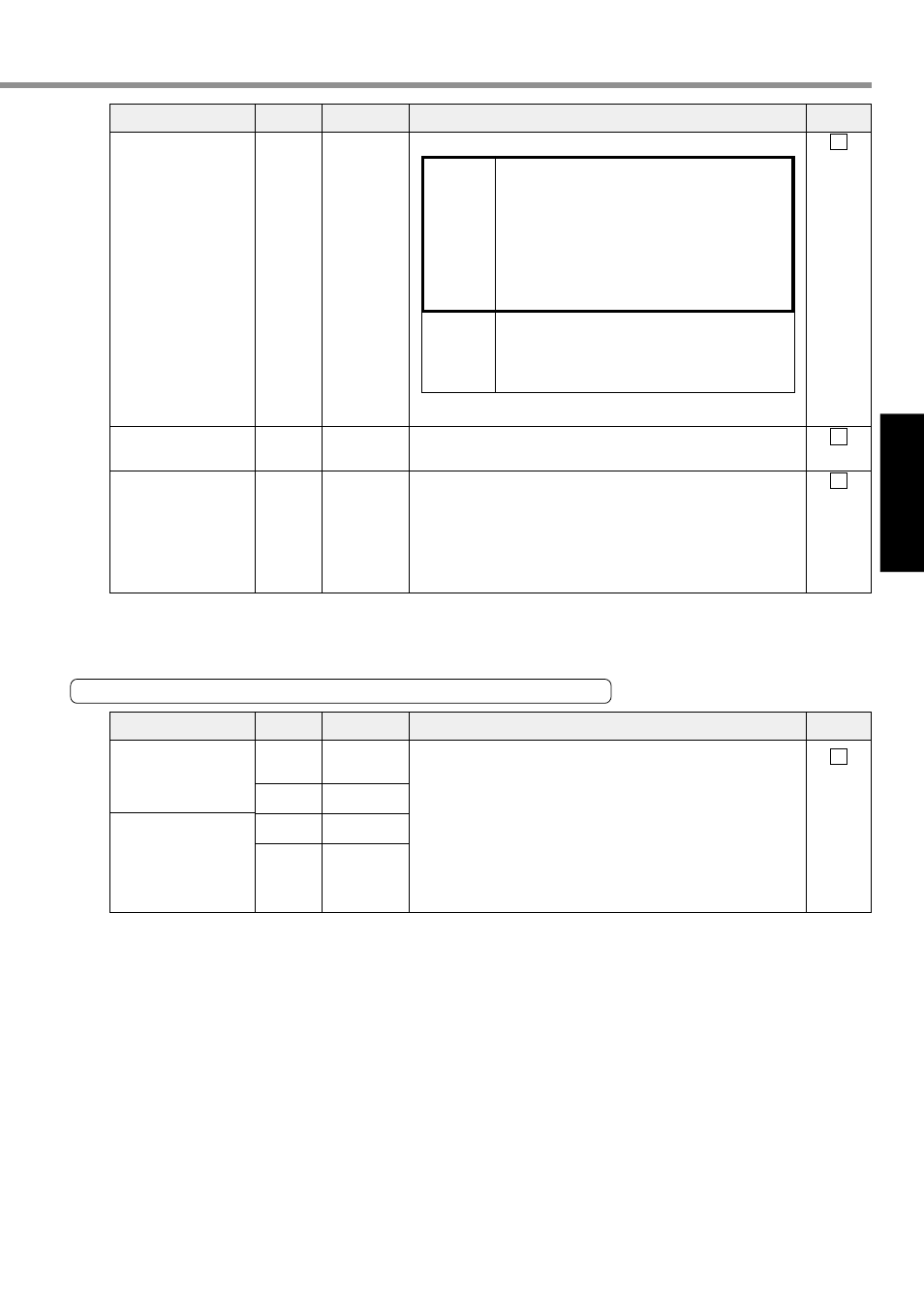
Input Signal (Related to Position Control) and its Functions
Signal Name
Command Pulse Input
Command sign input
• Input terminal of command pulse. The signal is received by the
high-speed photo coupler on the driver side.
• Allowable Input Highest Frequency
At the time of the line driver input : 500kpps
At the time of the open collector input
: 200kpps
• Input impedance of PULS and SIGN is 220
Ω.
• The following 3 forms of command pulse input can be selected
with Pr42 (command pulse input mode set up).
(1) 2-phase (Phase A/B) input
(2) CW (PULS)/CCW (SIGN) pulse input
(3) Command pulse (PULS)/sign (SIGN) input
22
23
24
25
PULS1
PULS2
SIGN1
SIGN2
PI
Page 68
Pin No.
Symbol
Function
I/F Circuit
Signal Name
Command Dividing
Multiplier Switching/
I n t e r n a l C o m m a n d
Speed Selection 1 In-
put
CW Overtravel Inhibit
Input
CW Overtravel Inhibit
Input
The control mode can change functions.
You must not enter any command pulse for 10 ms before or after
switching.
• If you open connection with COM- when a moving part of the
machine exceeds the movable range in CW direction, no torque
will be generated in CW direction.
• If you open connection with COM- when a moving part of the
machine exceeds the movable range in CCW direction, no torque
will be generated in CCW direction.
• If you set 1 to Pr04 (Overtravel input inhibit), CWL/CCWL inputs
will be invalid. A default value is invalid (1).
• Setting of Pr66 (DB inaction during driving prohibition) can acti-
vate the dynamic brake when CWL/CCWL input is valid. Ac-
cording to a default value, the dynamic brake will run (Pr66 is 0).
6
7
8
SI
Page 68
SI
Page 68
SI
Page 68
Pin No.
Symbol
Function
I/F Circuit
DIV
/INTSPD1
CWL
CCWL
Position
Control
• Input to switch dividing multiply of command
pulse
• When this signal is connected to COM-, it
will switch a command dividing multiply
numerator from Pr46 (Numerator of 1st
command pulse ratio) to Pr47 (Numerator of
2nd command pulse ratio).
You must not enter any command pulse for
10 ms before or after switching.
Internal
Velocity
Control
• With internal command speed selection 1
(INTSPD1), four-speed can be set in
combination with INTSPD 2.
• For details on settings of control mode, refer
to Page 117.