Connections and settings in position control mode, This represents a twisted pair cable. Page 75
Page 75
75
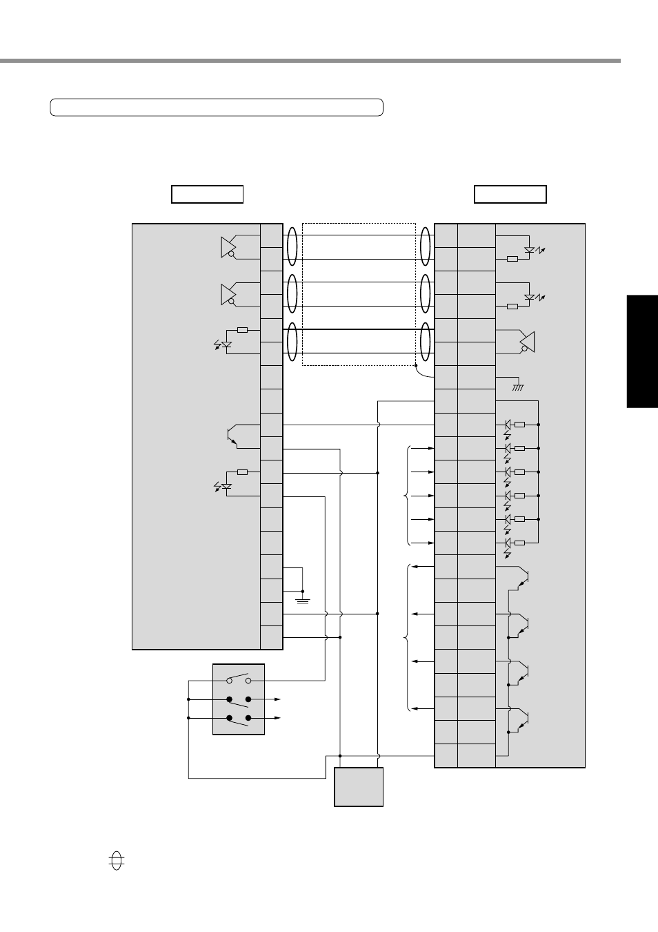
[Connections and Settings in Position Control Mode]
Connections and
Settings in Position
Control Mode
Origin proximity
sensor
CW limit sensor
CCW limit sensor
220
CW pulse command
output
CCW pulse command
output
A1
B1
A2
B2
A5
B5
A6
B6
A7
B7
A19
B19
A20
B20
Origin input
Deviation counter reset
output
PLC
FP2-PP2 AFP2430(Matsushita Electric Works, Ltd.)
Driver
E-series
External power input
FG
FG
24V+
24V–
To PLC
I/O input
1.6k
220
Ω
220
Ω
4.7k
Ω
4.7k
Ω
4.7k
Ω
4.7k
Ω
4.7k
Ω
4.7k
Ω
PULS1
PULS2
SIGN1
SIGN2
OZ+
OZ–
GND
COM+
CL
SRV-ON
GAIN/TC
A-CLR
CCWL
CWL
ALM
COIN
BRKOFF
WARN
COM–
22
23
24
25
19
20
14
1
4
2
5
3
8
7
9
10
11
12
13
From PLC
I/O output
To PLC
I/O input
Origin proximity input
GND +24V
DC24V
power supply
CW pulse
command
input
CCW pulse
command
input
Counter
clear input
Servo-ON
input
Servo alarm
output
Positioning
completion output
Brake release
output
Gain switching
input/torque limit
switching input
Alarm clear
input
Phase Z
output
Warning output
CW overtravel
inhibit input
CCW overtravel
inhibit input
Matsushita Electric Works, Ltd. FP2-PP2 AFP2430
This represents a twisted pair cable.