Test run with connector cn x5 connected, Wiring diagram parameters input signal status – Panasonic MINAS E-series User Manual
Page 111
111
[Connections and Settings in Internal Velocity Control Mode]
Connections and
Settings in Internal
V
e
locity Control Mode
Test Run with Connector CN X5 Connected
(1) Connect CN X5.
(2) Connect the control signal (COM+/COM-) to the power supply (12 to 24 VDC).
(3) Turn on the power (of the driver).
(4) Change the control mode to internal velocity control mode (Pr02=1).
(5) Activate Servo-ON by connecting Servo-ON input SRV-ON (CN X5 pin 2) and COM- (CN X5 pin 13). Then, with
switch of speed zero clamp input ZEROSPD (CN X5 pin 5) closed, run the motor. It will rotate at a speed
selected by combining internal command speed selection 1 INTSPD 1 (CN X5 pin 6) and internal command
speed selection 2 INTSPD 2 (CN X5 pin 4).
(6) Check rotation speed of the motor either on the monitor screen of PANATERM
®
or that of the console.
• Check that the motor rotates at a correct rate and in a correct direction.
(7) Ensure that the motor will stop when you open the speed zero clamp input ZEROSPD.
(8) If you wish to change rotation speed or rotation direction, reset the following parameters: See Pr53 to 56, speed
setting, 1st to 4th speed, on Page 117.
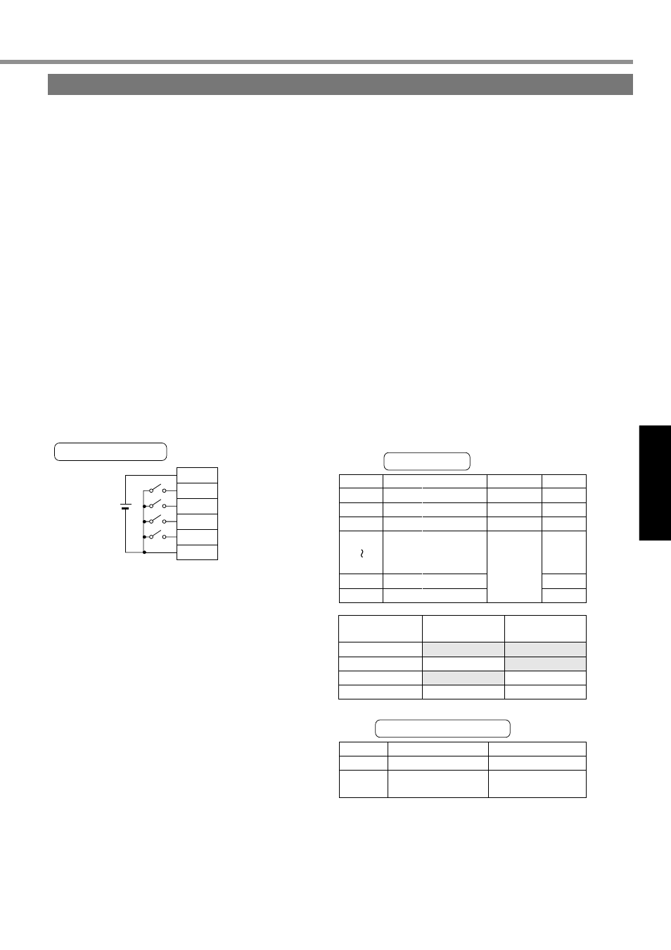
COM+
SRV-ON
ZEROSPD
INTSPD2
INTSPD1
COM—
1
2
4
6
13
5
DC
12V - 24V
PrNo.
Pr02
Pr04
Pr06
Pr53
Pr56
Pr58
Pr59
Parameter Name
Control mode setup
Overtravel input inhibit
ZEROSPD input selection
Acceleration time
Deceleration time
Settings
1
1
1
Default setup
value
2
1
1
0
0
0
Signal No.
00
05
Input Signal Name
Servo-ON
Speed zero clamp
Monitor Display
+ A
—
(Stop at +A.)
Internal velocity
1st speed (Pr53)
INTSPD1
(Pin 6)
Open
Closed
Open
Closed
INTSPD2
Open
Open
Closed
Closed
The motor runs
when ZEROSPD
switch is closed,
while it stops when
the switch is open.
1st speed setting
to 4th speed
Set this, as
necessary
2nd speed (Pr54)
3rd speed (Pr55)
4th speed (Pr56)
(Pin 4)
Wiring Diagram
Parameters
Input Signal Status